Method of Uniform Crimping and Expansion of Medical Devices

a technology of medical devices and uniform crimping, applied in the field of medical devices, can solve the problems of ring struts and/or cell structures, unable to consistently expand in a uniform manner, early crimping processes, etc., to avoid the potential formation of broken struts, improve balloon folding, and increase the uniformity of polymer scaffold expansion

Active Publication Date: 2014-04-10
ABBOTT CARDIOVASCULAR
View PDF9 Cites 44 Cited by
  • Summary
  • Abstract
  • Description
  • Claims
  • Application Information

AI Technical Summary

Benefits of technology

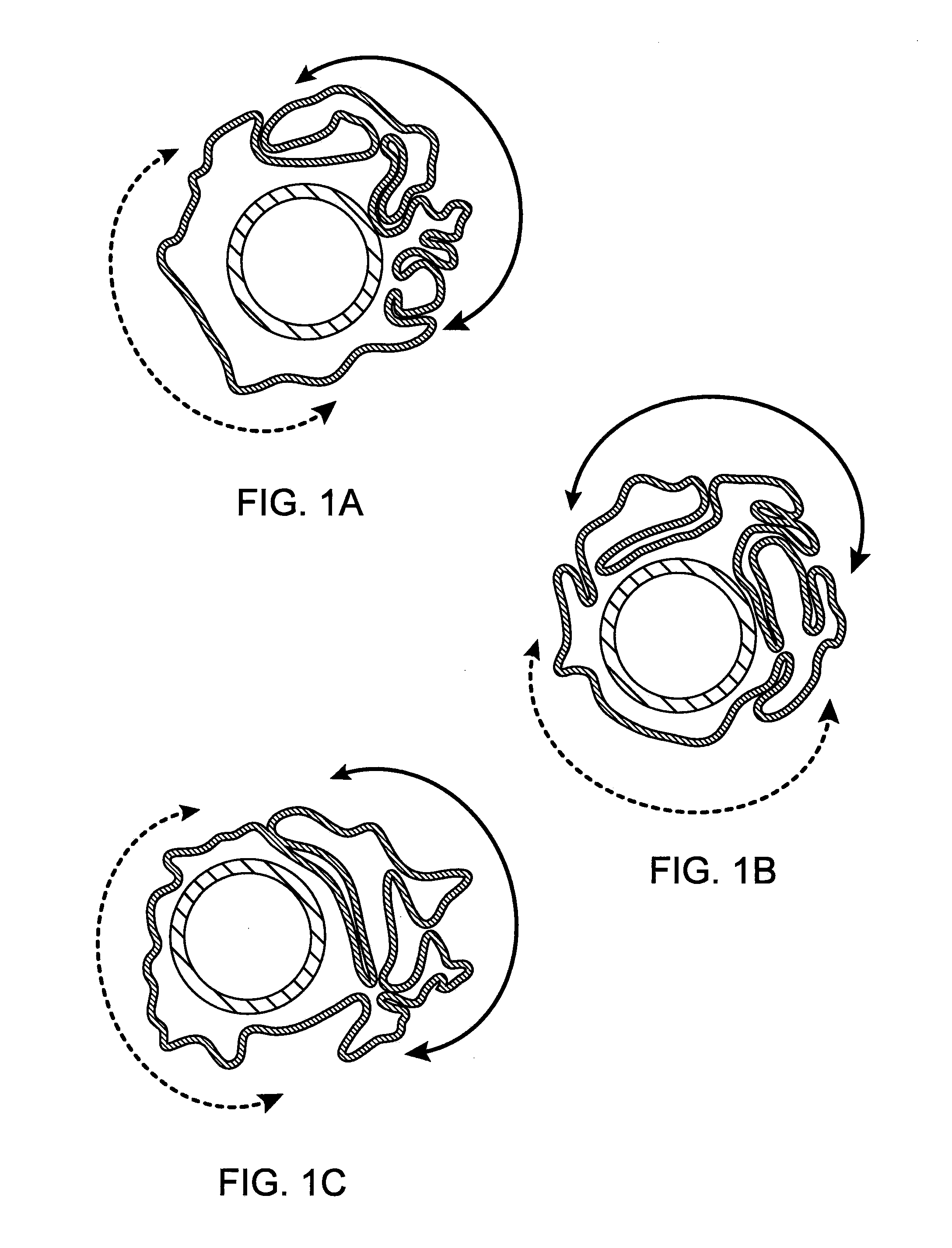
[0016]The invention provides methods for increasing uniformity of polymer scaffold expansion via uniform scaffold crimping and improved balloon folding within the crimped scaffold to avoid the potential formation of broken struts, while maintaining or improving upon scaffold-balloon retention.
[0019]Structural integrity: avoiding damage to the scaffold's structural integrity when the scaffold is crimped to the balloon, or expanded by the balloon.
[0020]Safe delivery to an implant site: avoiding dislodgement or separation of the scaffold from the balloon during transit to an implant site and having a small crossing profile for the catheter.
[0021]Uniformity of expansion: avoiding non-uniform expansion of scaffold rings, which can lead to structural failure and / or reduced fatigue life.
[0027]Further, in accordance with this preferred embodiment, to achieve the lowest possible crossing profile and prevent balloon overstretch and / or formation of pinholes, it is found that the balloon pressure should be released when the scaffold diameter is still relatively large (e.g., more than 50% of the non-crimped scaffold). If the pressure is released too late, too much balloon material can become trapped among struts of the scaffold, which can not only result in a larger crossing profile, but also can overstretch and create pin holes in the balloon. Additionally, it is also preferred to begin to reduce pressure during a dwell period just prior to deflating the balloon (e.g., from 70 psi to 50 psi or lower). For the preferred embodiment, it was found that with the foregoing type of control of the crimping process a more effective balloon-scaffold engagement results; that is, one can achieve a better balance among achieving a low crossing profile, high scaffold-balloon retention force and uniform scaffold expansion, while avoiding damage to the balloon material. According to another embodiment, the crimping steps may include only 1, or only 3, or at most three dwell periods between an initial diameter reduction and final diameter reduction.

Problems solved by technology

Regarding the uniformity of expansion requirement, it has been recently found that earlier crimping processes, while satisfying the other two requirements, have not consistently expanded in a uniform manner when the balloon is expanded.
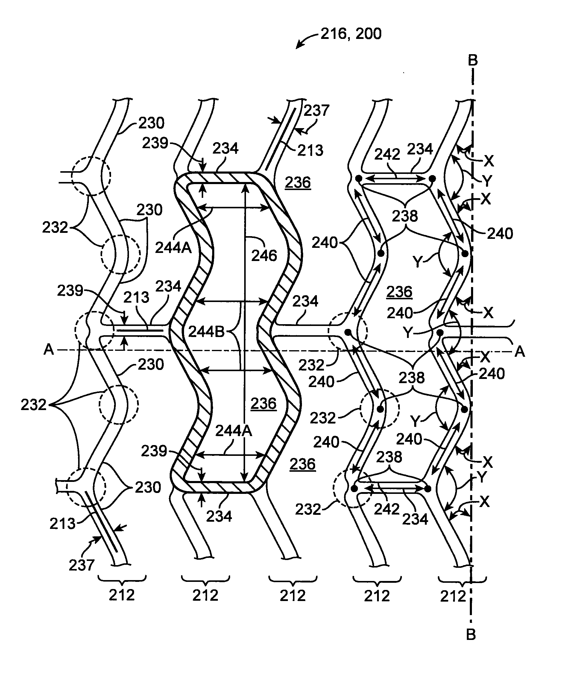
As a consequence, ring struts and / or cell structures, which provide radial strength and stiffness for the scaffold, inherit an un-even distribution of stresses and strains.
The balloon-induced stresses and strains associated with over-expanded cells can exceed the material's ultimate stress and strain level at deployment, which might potentially result in crack formation, fracture or a reduced fatigue life or fracture toughness, in which case fracture can occur immediately, after a few days, or weeks after implantation.

Method used


Image

  • Method of Uniform Crimping and Expansion of Medical Devices
  • Method of Uniform Crimping and Expansion of Medical Devices
  • Method of Uniform Crimping and Expansion of Medical Devices

Examples


example 1

[0072]FIGS. 3A-3B illustrate steps associated with a first crimping process according to the disclosure. In this example there is a crimping process described for crimping a 3.5 mm scaffold to a 3.0 mm semi-compliant PEBAX balloon. FIG. 3B illustrates in graphical form the crimping portion of the FIG. 3A flow—a graph of scaffold diameter verses time with a balloon pressure of between about 20-70 psi (or 1 atm up to the fully or over-inflated balloon pressure) applied throughout substantially all of the crimping process. For example, the balloon pressure is maintained at 70 psi for steps A-G, then the pressure is allowed to decrease (or deflated) to 50 psi (or 1 atm) for the period G-H. Balloon pressure is removed at point H. No balloon pressure is used H-J for purposes of achieving a low crossing profile and avoiding damage to the balloon.

[0073]FIG. 3A (as well as FIG. 4A, discussed infra) indicate three possibilities for crimping, depending on need. First, there are two balloons us...

example 2

[0095]FIGS. 4A-4B illustrate the steps associated with another example of a crimping process according to the preferred embodiments. FIG. 4B illustrates in graphical form the crimping portion of the FIG. 4A flow—a graph of scaffold diameter verses time. As with the previous example, a balloon pressure of between about 20-70 psi is applied throughout substantially all of the crimping process. In this case, balloon pressure is maintained until the scaffold diameter has reached about 50% of its original diameter. Additionally, in this example, following the final alignment check the iris diameter is continuously reduced at a slow rate until reaching the final crimping diameter, and then continuous reduced further after balloon pressure is relieved. Otherwise this process is essentially the same as in Example 1.

[0096]According to the disclosure the balloon is fully or over inflated before the scaffold diameter is reduced within the crimper, or after a partial crimping and final alignmen...


PUM

PropertyMeasurementUnit
pressureaaaaaaaaaa
crimping temperatureaaaaaaaaaa
temperaturesaaaaaaaaaa

Abstract

A medical device-includes a scaffold crimped to a catheter having an expansion balloon. The scaffold is crimped to the balloon by a process that includes one or more balloon pressurization steps. The balloon pressurization steps are selected to enhance scaffold retention to the balloon, maintain a relatively uniform arrangement of balloon folds about the inner surface of the crimped scaffold so that the scaffold expands in a uniform manner when the balloon is inflated, and to avoid any possible over-stretching of balloon material.

Description

BACKGROUND OF THE INVENTION[0001]1. Field of the Invention[0002]The present invention relates to medical devices; more particularly, this invention relates to processes for uniformly crimping and deploying a medical device, such as a polymeric scaffold, to and from, respectively, a delivery balloon.[0003]2. Background of the Invention[0004]The art recognizes a variety of factors that affect a polymeric scaffold's / stent's ability to retain its structural integrity when subjected to external loadings, such as crimping and balloon expansion forces. According to the art, characteristics differentiating a polymeric, bio-absorbable scaffolding of the type expanded to a deployed state by plastic deformation from a similarly functioning metal stent are many and significant. Indeed, several of the accepted analytic or empirical methods / models used to predict the behavior of metallic stents tend to be unreliable, if not inappropriate, as methods / models for reliably and consistently predicting...

Claims


Application Information

Patent Timeline
Patent Type & Authority Applications(United States)
IPC IPC(8): B23P11/02A61F2/958A61M25/10
CPCA61F2/91Y10T29/49863A61F2/958A61F2/9522A61F2002/9583A61M25/1025B23P11/00
Inventor WANG, YUNBING
Owner ABBOTT CARDIOVASCULAR
Why Eureka
Try Eureka