Polarizing plate and liquid crystal display

a technology of liquid crystal display and polarizing plate, which is applied in the direction of polarizing elements, instruments, optics, etc., can solve the problems of peeling of the polarizing plate, uneven brightness, and light leakage on the four corners of the liquid crystal panel, and achieve the effect of suppressing light leakag

Active Publication Date: 2014-04-10
FUJIFILM CORP
View PDF3 Cites 37 Cited by
  • Summary
  • Abstract
  • Description
  • Claims
  • Application Information

AI Technical Summary

Benefits of technology

[0008]An object of the invention is to provide a polarizing plate which is capable of suppressing light leakage caused by the above-described heat cycle.
[0010]As a result of further investigation, the present inventors found that the above-described problems can be solved by reducing the moisture vapor permeability of the polarizing plate on the viewing side to delay water absorption and drying, reducing the creep amount of the adhesive layer to suppress the expansion thereof, and suppressing the shrinkage of the polarizing plate.
[0022]According to the invention, it is possible to provide a polarizing plate capable of suppressing light leakage which occurs in four corners of a liquid crystal panel due to a heat cycle where a high-temperature high-humidity environment and an ordinary-temperature ordinary-humidity environment are repeated.

Problems solved by technology

As a result, there is a problem in that light leakage occurs on four corners of the liquid crystal panel.
As a countermeasure of this problem, the solving means described in JP2008-249901A is not sufficient.
The adhesive layer having a relatively large creep amount is used to relax the warpage of the liquid crystal panel, but the peeling of the polarizing plate and unevenness in brightness are likely to occur.
Accordingly, it is difficult to solve the peeling of the polarizing plate and unevenness in brightness while improving the warpage of the panel.
Therefore, a liquid crystal panel is gradually warped, which leads to light leakage on four corners of the liquid crystal panel.

Method used


Image

  • Polarizing plate and liquid crystal display
  • Polarizing plate and liquid crystal display
  • Polarizing plate and liquid crystal display

Examples


examples

[0367]Hereinafter, the invention will be described in detail referring to examples. In the following examples, materials, reagents, the amounts of the materials and the ratios thereof, operations, and the like can be appropriately changed within a range not departing from the concepts of the invention. Therefore, the scope of the invention is not limited to the following specific examples.

[0368][Preparation of Polarizing Plate Protective Film LA1]

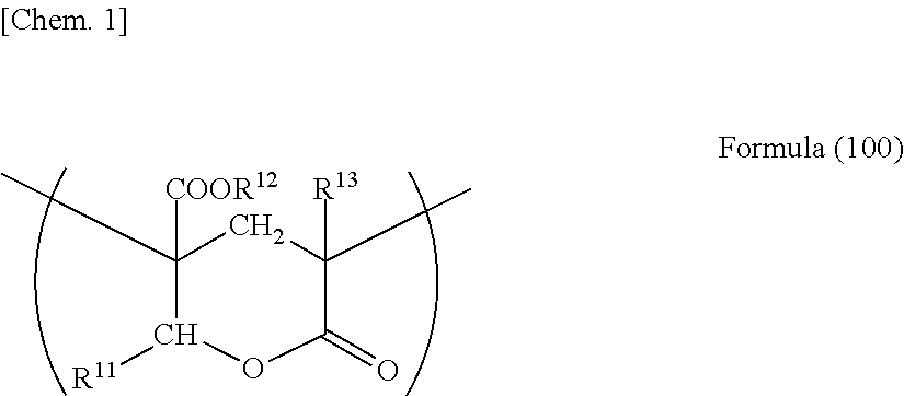
[0369]90 parts by mass of (meth)acrylic resin (mass ratio of copolymerizable monomers: methyl methacrylate / methyl 2-(hydroxymethyl)acrylate=8 / 2, lactone cyclization ratio: about 100%, content of lactone ring structure: 19.4%, weight average molecular weight: 133000, melt flow rate: 6.5 g / 10 min (240° C., 10 kgf), Tg: 131° C.) having a lactone ring structure represented by the following formula (IA); and 10 parts by mass of acrylonitrile-styrene (AS) resin (TOYO AS AS20, manufactured by Toyo-Styrene Co., Ltd.) were mixed with each other to o...


PUM

PropertyMeasurementUnit
temperatureaaaaaaaaaa
thicknessaaaaaaaaaa
thicknessaaaaaaaaaa

Abstract

A polarizing plate according to the invention includes a first protective film; a polarizer; a second protective film; and an adhesive layer in this order, in which a moisture vapor permeability of the first protective film is less than or equal to 200 g / m2 / 24 hours, the second protective film contains cellulose acylate as a major component, a creep amount of the adhesive layer is less than 100 μm, and a shrinkage force of the polarizing plate in an absorption axis direction thereof which is represented by the following expression (A) is lower than or equal to 2000 N / m. Expression (A) is the Shrinkage Force (N / m) of Polarizing Plate in Absorption Axis Direction=Elastic Modulus (GPa) of Polarizing Plate in Absorption Axis Direction×|Humidity Dimensional Change Rate (%) of Polarizing Plate in Absorption Axis Direction|×Thickness (μm) of Polarizing Plate×10.

Description

BACKGROUND OF THE INVENTION[0001]1. Field of the Invention[0002]The present invention relates to a polarizing plate and a liquid crystal display.[0003]2. Description of the Related Art[0004]In general, a polarizing plate of a liquid crystal display has a configuration in which a transparent protective film (polarizing plate protective film) is bonded to both front and back surfaces of a polarizer, the polarizer including a polyvinyl alcohol film on which iodine or a dye is adsorbed and aligned. As the polarizing plate protective film, a film of cellulose acylate represented by cellulose acetate is widely used because this film has high transparency and can easily secure adhesion with polyvinyl alcohol which is used in the polarizer.[0005]Along with the growth of the liquid crystal display market, performance requirements for the above-described polarizing plate have become strict. In particular, since the dimensional change of the polarizing plate caused by the effects of temperatur...

Claims


Application Information

Patent Timeline
Patent Type & Authority Applications(United States)
IPC IPC(8): G02F1/1335G02B5/30
CPCG02B5/30G02F1/133528G02B1/105G02B5/3033G02B1/14G02F1/133562
Inventor HISANAGA, KAZUYAINOUE, RIKIOISHIGURO, MAKOTO
Owner FUJIFILM CORP
Why Eureka
Try Eureka