
Excitation unti fir a fiber laser

Inactive Publication Date: 2014-04-24
BERGER ROLAND
View PDF7 Cites 1 Cited by
  • Summary
  • Abstract
  • Description
  • Claims
  • Application Information

AI Technical Summary

Benefits of technology

The present invention aims to improve the efficiency of a fiber laser by eliminating the need for an intermediate fiber coupling for pumping. The invention provides an excitation unit that includes an excitation fiber that forms a two-dimensional or three-dimensional structure in the resonator region of the fiber laser. The excitation fiber runs through each excitation chamber at least once and is held in holding units laterally to each chamber. The excitation unit includes a base plate on which a plurality of excitation housings are provided, each forming a gas-tight excitation chamber. The excitation fiber is designed to have a reflector element at its first fiber end and an out-coupling mirror element at its second fiber end. The excitation unit improves the efficiency of the fiber laser by allowing for a perpendicular pump light source and a translucent housing window.

Problems solved by technology

The efficiency of the light in-coupling is likely to be extremely poor in this case due to the presence of the sheathing of the laser active fiber.

Method used


Image

  • Excitation unti fir a fiber laser
  • Excitation unti fir a fiber laser
  • Excitation unti fir a fiber laser

Examples


Embodiment Construction

)

[0040]In describing the preferred embodiment of the present invention, reference will be made herein to FIGS. 1-8 of the drawings in which like numerals refer to like features of the invention.

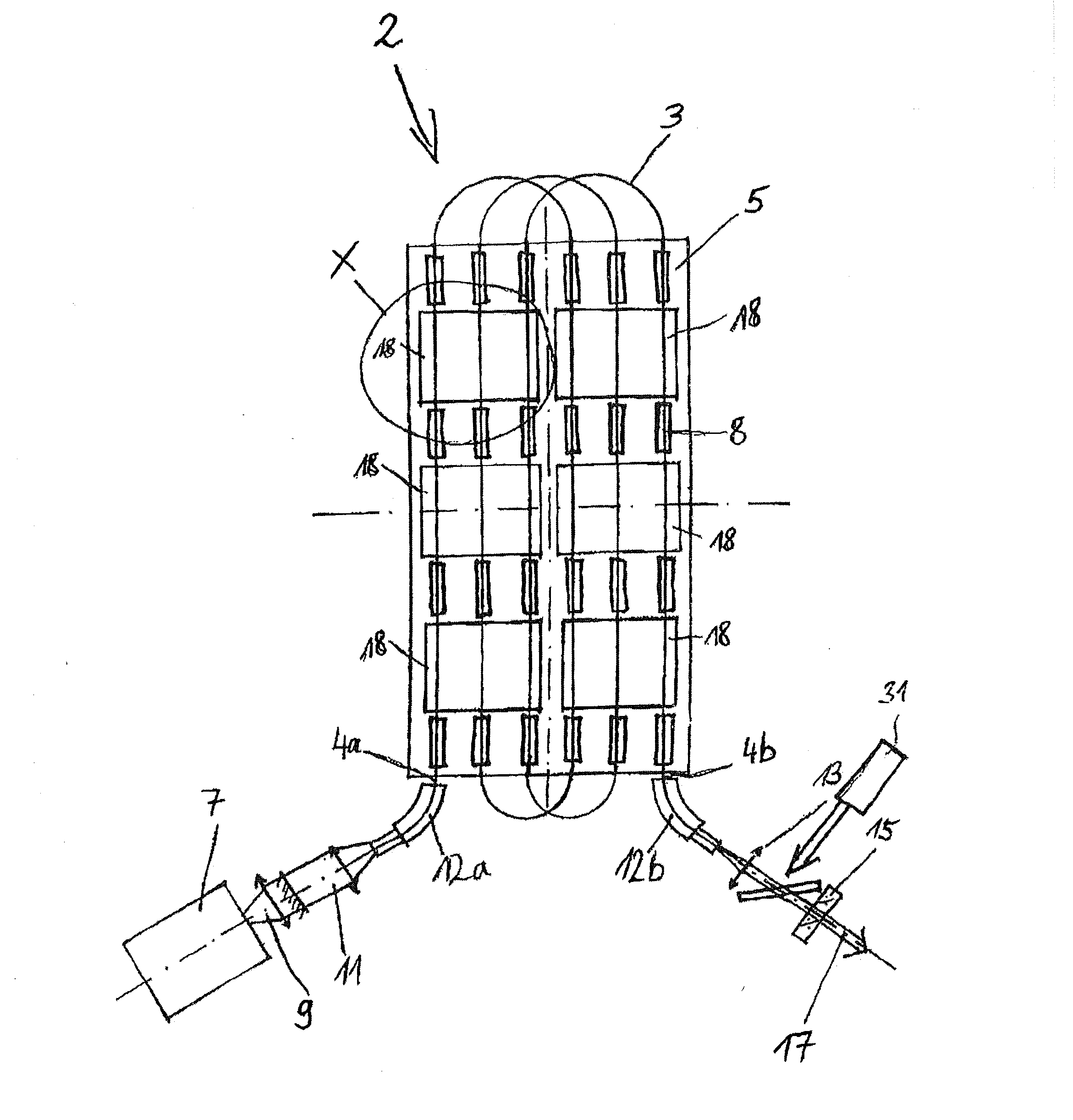
[0041]FIG. 1 shows a top view of an excitation unit 2 in accordance with the invention. In addition to this excitation unit 2 the fiber laser contains a housing, an energy supply and a cooling system, which are not shown for reasons of clarity.

[0042]One can see an active fiber or excitation fiber 3, which in this embodiment is arranged in several loops over a base plate 5.

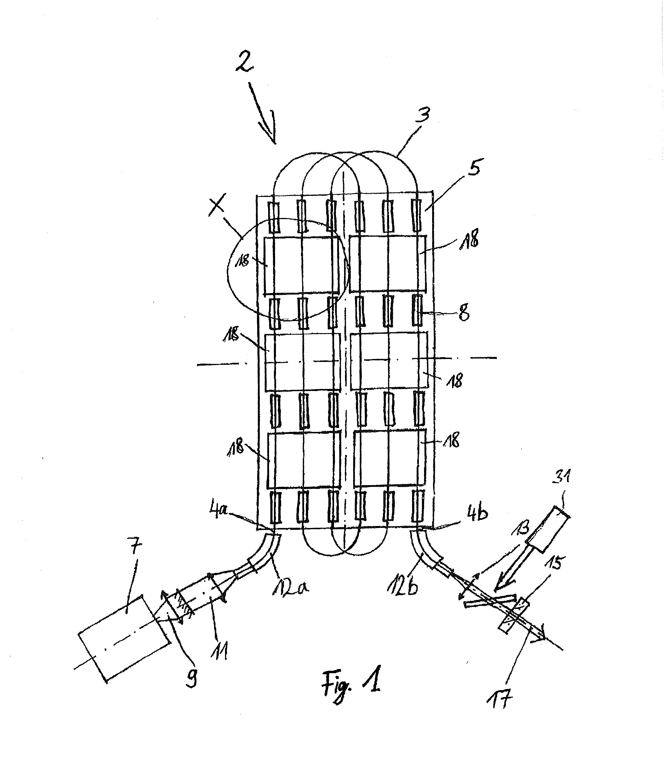
[0043]The excitation fiber 3 has a first fiber end 4a and a second fiber end 4b. “X” marks a region of an excitation housing 18, which will be explained in more detail in connection with FIG. 2.

[0044]A longitudinal pump light source 7 is shown which, for example, can be realized in the form of a diode laser and emits a longitudinal pump beam 9, which is coupled into the excitation fiber 3 in the region of the first fiber end...


PUM


Abstract

An excitation unit for a fiber laser having an excitation fiber and forming a two-dimensional or three-dimensional structure in a resonator region of the fiber laser. In cross-section, the excitation fiber has an active fiber core, a pump cladding that surrounds the active core, a quartz glass casing that surrounds the pump cladding, and at least one cover. The resonator region is equipped with a base plate having a plurality of excitation housings, each housing delimiting a gas-tight excitation chamber. The excitation fiber runs through each excitation chamber and is held in holding units. The excitation chambers are formed in an elliptical manner. The excitation housings are provided with a translucent window, and a transversal pump light source is arranged in the region of each translucent window such that a pump light that leaves the pump light source impinges the longitudinal axis of the excitation fiber in a perpendicular manner.

Description

BACKGROUND OF THE INVENTION[0001]1. Field of the Invention[0002]The present invention relates to an excitation unit for a fiber laser.[0003]2. Description of Related Art[0004]Fiber lasers are a special form of solid state laser. Put simply, a fiber laser, more precisely the resonator of a fiber laser, consists of a glass fiber which has a doped core and a cladding. The doped core of the glass fiber thereby forms the active medium. It is thus a solid state laser with optical waveguide properties. Due to the relatively great length (high aspect ratio) of the fiber laser, the pump light, which is fed into the resonator of the fiber laser through a pump optic, causes an excitation of the active medium.[0005]Fiber lasers are optically pumped in that rays, for example from diode lasers, are coupled in, usually coaxially to the fiber core, into its cladding, or into the core itself. Double clad fibers permit a higher power to be achieved; from the innermost of the two claddings, the pump b...

Claims


Application Information

Patent Timeline
IPC IPC(8): H01S3/0941
CPCH01S3/0941H01S3/0404H01S3/0407H01S3/042H01S3/06704H01S3/094007H01S3/094015H01S3/094019H01S3/09408H01S3/09415
Inventor BERGER, ROLAND
Owner BERGER ROLAND
Features
  • Generate Ideas
  • Intellectual Property
  • Life Sciences
  • Materials
  • Tech Scout
  • Unparalleled Data Quality
  • Higher Quality Content
  • 60% Fewer Hallucinations
Learn More