Controllable automatic umbrella unfolding device

a technology of automatic umbrella unfolding and controllable device, which is applied in the direction of walking sticks, etc., can solve the problems of high breakage possibility of umbrella rope and slow opening speed, and achieve the effect of simple structure, easy operation and controllable strok

Active Publication Date: 2014-05-01
MA ZHUNAN
View PDF11 Cites 3 Cited by
  • Summary
  • Abstract
  • Description
  • Claims
  • Application Information

AI Technical Summary

Benefits of technology

[0007]The present invention has the beneficial effects that: the device accomplishes stroke control by controlling the valve of the gas spring via the lever, so that the stroke can be stopped at any position; compared with the conventional devices, the device with no crank, umbrella rope and pull lever has the advantages of automatic umbrella unfolding, controllable stroke, simple structure, very few components and relatively low cost

Problems solved by technology

A traditional sunshade umbrella is opened in such a manner of: driving the umbrella rope and the pull lever through an umbrella unfolding crank, and then pushing by hand; such a crank-opening way has the defects of troublesome umbrella unfolding, slow opening speed and high breakage possibility of the umbrella rope; there is another pull lever-type opening and closing device, which, however, is high in umbrella position after pull lever-type closing and also quite inconvenient.

Method used


Image

  • Controllable automatic umbrella unfolding device
  • Controllable automatic umbrella unfolding device
  • Controllable automatic umbrella unfolding device

Examples


embodiment 1

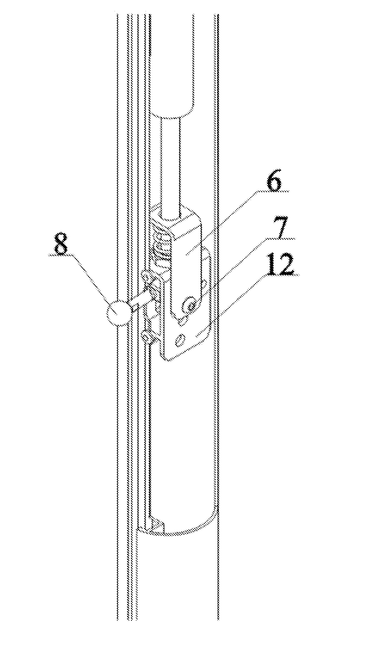
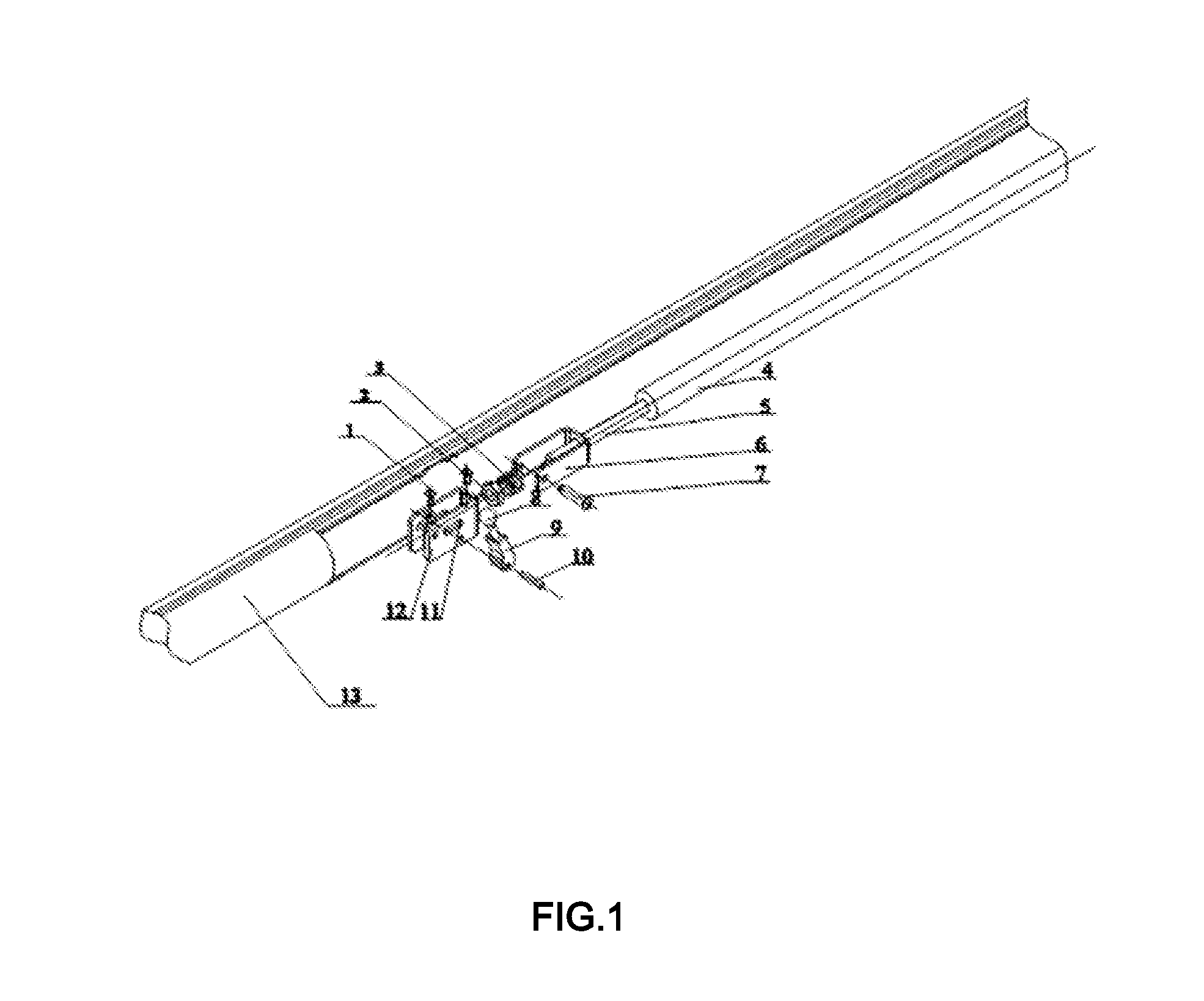
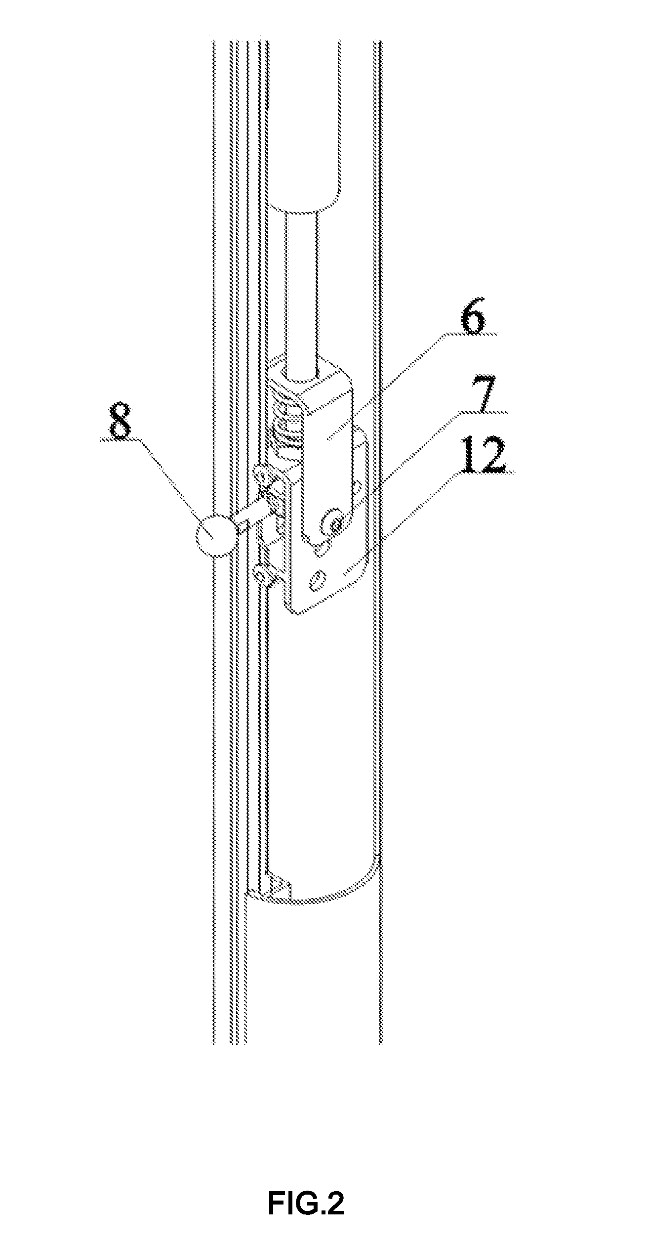
[0015]As shown in FIG. 1, FIG. 2, FIG. 3, FIG. 4 and FIG. 5, a controllable automatic umbrella unfolding device comprises an upper runner 18, a middle runner 19, a lower runner 20 and a center bar 13. The upper runner 18 of the umbrella is fixed at the top end of the center bar 13. The middle runner 19 and the lower runner 20 of the umbrella are movably sleeved on the center bar 13. The upper runner 18 is connected with long ribs 15. The long ribs 15 are connected with short ribs 16. The middle runner 19 is connected with branch ribs 17. The branch ribs 17 are connected with the short ribs 16. The short ribs 16 are connected with the lower runner 20. A gas spring is disposed in the center bar 13. The tail end of a cylinder barrel 4 of the gas spring is connected with the middle runner 19 of the umbrella. A valve 14 is arranged at the end of a piston rod 5 of the gas spring. A valve opening device is disposed corresponding to the valve 14. The valve opening device comprises a gas spr...


PUM


Abstract

The present invention relates to the field of parts of a sunshade umbrella, in particular to a controllable automatic umbrella unfolding device, which comprises an upper runner, a middle runner, a lower runner and a center bar. The upper runner of the umbrella is fixed at the top end of the center bar, the middle runner and the lower runner of the umbrella are movably sleeved on the center bar, the upper runner is connected with long ribs, the long ribs are connected with short ribs, the middle runner is connected with branch ribs, the branch ribs are connected with the short ribs, the short ribs are connected with the lower runner, a gas spring is disposed in the center bar, the tail end of a cylinder barrel of the gas spring is connected with the middle runner of the umbrella, a valve is arranged at the end of a piston rod of the gas spring, and a valve opening device is disposed corresponding to the valve. The automatic umbrella unfolding device has the beneficial effects of: automatic umbrella unfolding, controllable stroke, simple structure, very few components and relatively low cost.

Description

TECHNICAL FIELD[0001]The present invention relates to the field of parts of a sunshade umbrella, in particular to a controllable automatic umbrella unfolding device.BACKGROUND[0002]A traditional sunshade umbrella is opened in such a manner of: driving the umbrella rope and the pull lever through an umbrella unfolding crank, and then pushing by hand; such a crank-opening way has the defects of troublesome umbrella unfolding, slow opening speed and high breakage possibility of the umbrella rope; there is another pull lever-type opening and closing device, which, however, is high in umbrella position after pull lever-type closing and also quite inconvenient. In the early Chinese patent of the applicant: Umbrella unfolding and Closing Device (Patent Number: ZL200420107976.0) and the subsequent improved Chinese patent: Umbrella unfolding and Closing Device (Patent Number: ZL200520116792.5), an umbrella unfolding and closing way that is different from the traditional operation ways is ado...

Claims


Application Information

Patent Timeline
Patent Type & Authority Applications(United States)
IPC IPC(8): A45B25/16
CPCA45B25/165A45B25/143
Inventor MA, ZHUNAN
Owner MA ZHUNAN
Why Eureka
Try Eureka