Power conversion device

a power conversion device and power technology, applied in the direction of electric cable installation, electric apparatus casing/cabinet/drawer, electric cable installation, etc., can solve the problems of reducing the size of the power conversion device, the inability to achieve the inductance reduction effect in the overlapping portion, and the inability to achieve the inductance reduction effect, etc., to achieve easy prevention of interference between the resin mold section and the capacitor terminal, simplify the shape of the capacitor terminal, and improve the freedom of wiring bus bar

Active Publication Date: 2014-05-01
DENSO CORP
View PDF11 Cites 16 Cited by
  • Summary
  • Abstract
  • Description
  • Claims
  • Application Information

AI Technical Summary

Benefits of technology

[0014]The bending section can be provided in the bus bar. In this instance, the shape of the capacitor terminal can be simplified.
[0015]The bus bar can be partially sealed by a resin mold section. The bending section can be exposed from the resin mold section. In this instance, insulation between the bus bar and areas that should be electrically insulated from the bus bar can be easily ensured. Freedom in wiring of the bus bar can be improved. Because the bending section is exposed from the resin mold section, interference between the resin mold section and the capacitor terminal can be easily prevented. Therefore, the shape of the capacitor terminal can be simplified, and the current path between the capacitor and the main circuit section can be shorted. As a result, inductance on the current path can be more easily reduced. In addition, when the bending section is configured to be exposed from the resin mold section, the bending section can be formed after the bus bar is resin-molded. Therefore, there is an advantage in that freedom of design is improved.
[0016]In addition, the tip direction of the connecting section can be made parallel with the array direction of the main circuit section and the capacitor. In this instance, the shape of the bus bar or the capacitor terminal can be easily simplified. In addition, because the connecting section does not project in the direction perpendicular to the array direction, the bulk in the direction perpendicular to the array direction can be reduced. The overall power conversion device can be made compact.
[0017]In addition, the capacitor main body can be configured such that the capacitor element and a sealing resin that seals the capacitor element are housed and disposed within a capacitor case having one open face. The capacitor element can be projected from the open face. The capacitor can be disposed such that the open face of the capacitor case faces the main circuit section. As a result of this configuration, the length of the current path of the capacitor element can be minimized. Inductance can be reduced. In addition, the shape of the capacitor element can be more easily simplified.
[0018]In addition, the main circuit section can be a stacked body in which the semiconductor module and a plurality of cooling members that cool the semiconductor module from both main surfaces are alternately stacked. The capacitor can be disposed on one end side of the main circuit section in the stacking direction of the stacked member. In this instance, size reduction of the power conversion device in the stacking direction can be achieved in addition to size reduction in the direction perpendicular to the stacking direction. In other words, as a result of the capacitor being disposed on one end of the main circuit section in the stacking direction of the stacked member, the dimension of the power conversion device in the direction perpendicular to the stacking direction can be reduced. On the other hand, as a result of the connection structure between the bus bar and the capacitor described above, the space between the main circuit section and the capacitor can be reduced, and the dimension of the power conversion device in the stacking direction can be minimized. The cooling member may be, for example, a cooling tube including a coolant flow path through which a cooling medium flows, or may be a heat sink composed of a heat-conducting member, such as a metal member.
[0019]In addition, the power conversion device preferably has a positive bus bar and a negative bus bar as the bus bars. The positive bus bar and the negative bus bar are preferably integrated by the resin mold section that partially seals the positive bus bar and the negative bus bar. In this instance, handling of the bus bar is facilitated. Assembly efficiency of the power conversion device can be improved.

Problems solved by technology

Therefore, an inductance reduction effect cannot be expected to be achieved in the overlapping portion.
As a result, size reduction of the power conversion device may become difficult.

Method used


Image

  • Power conversion device
  • Power conversion device
  • Power conversion device

Examples


first embodiment

[0037]A power conversion device according to a first embodiment of the present invention will hereinafter be described with reference to FIG. 1 to FIG. 6.

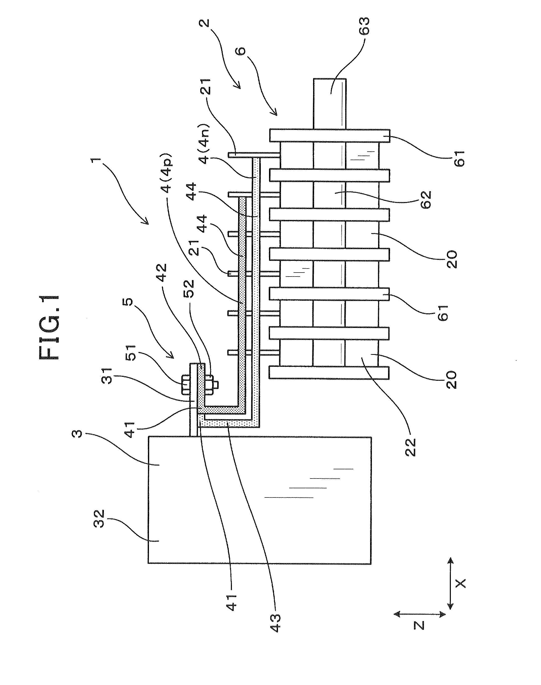
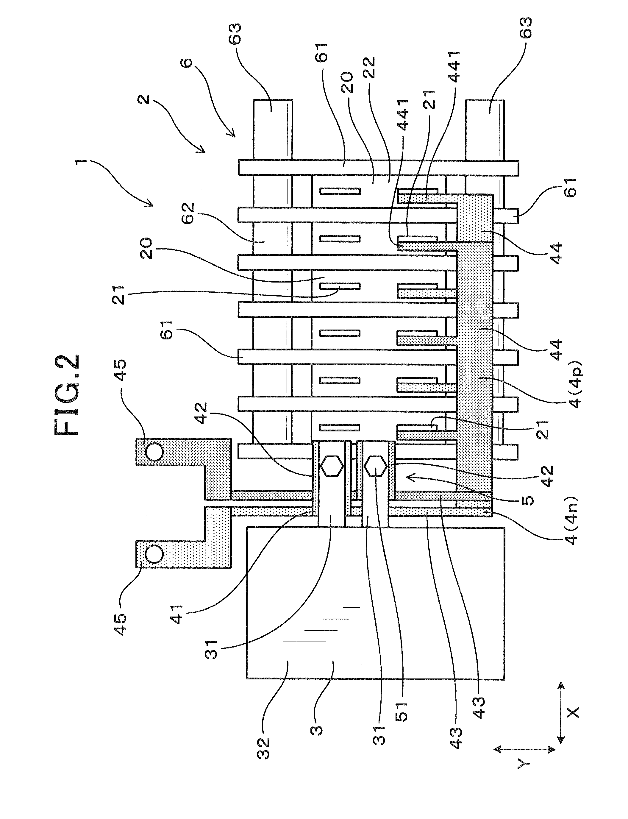
[0038]FIG. 1 illustrates a perspective view of the power conversion device according to the first embodiment. FIG. 2 illustrates a planar view of the power conversion device.

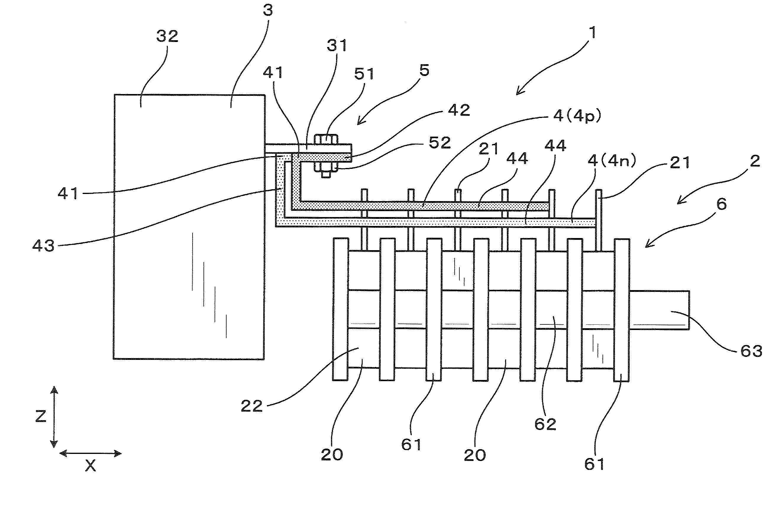
[0039]As shown in FIG. 1 and FIG. 2, a power conversion device 1 according to the first embodiment has a main circuit section 2, a capacitor 3, and a bus bar 4 that connects the main circuit section 2 and the capacitor 3. The main circuit section 2 has a semiconductor module 20. The semiconductor module 20 has a switching element therein and includes a main electrode terminal 21. The capacitor 3 has a capacitor element 320 therein and includes a capacitor terminal 31. The bus bar 4 connects the main electrode terminal 21 and the capacitor terminal 31.

[0040]FIG. 3 is a cross-sectional view of the capacitor 3 according to the first embodiment. As shown in FIG. 3,...

second embodiment

[0062]A power conversion device according to a second embodiment will hereinafter be described with reference to FIG. 7 to FIG. 10.

[0063]FIG. 7 illustrates a planar view of the power conversion device according to the second embodiment. FIG. 8 illustrates a cross-sectional view taken along line VIII-VIII and viewed from the arrow in FIG. 7. FIG. 9 illustrates a planar view of an assembly procedure of the power conversion device according to the second embodiment, FIG. 10 is a cross-sectional view taken along line A-A and viewed from the arrow in FIG. 9.

[0064]As shown in FIG. 7 to FIG. 10, the second embodiment is an example in which a terminal block 12 for the connecting section 5 is provided in the resin mold section 11. In other words, as shown in FIG. 7 and FIG. 8, the terminal block 12 is formed integrally with the resin mold section 11 in which the pair of bus bars 4 are molded. The terminal block 12 is configured such that the bus bar terminal 42 can be placed thereon in a sta...

third embodiment

[0070]The power conversion device 1 according to a third embodiment will be described with reference to FIG. 11 and FIG. 12. FIG. 11 is a perspective view of the power conversion device 1 according to the third embodiment. FIG. 12 illustrates a planar view of the power conversion device 1. As shown in FIG. 11 and FIG. 12, the third embodiment is an example in which bending sections 311 and 411 are provided in both the capacitor terminal 31 and the bus bar 4. According to the third embodiment, the bending sections 311 and 411 are both right angles. The bending sections 311 and 411 bend towards the lateral direction Y. The tip direction of the connecting section 5 between the capacitor terminal 31 and the bus bar terminal 42 faces the direction Y. In addition, the connecting section 5 protrudes further outward in the direction Y than the stacked member 6 and the capacitor main body 32. Other configurations are similar to those according to the first embodiment. Among the reference num...


PUM


Abstract

A power conversion device comprises a main circuit section that has a semiconductor module with a switching element therein and including a main electrode terminal, a capacitor with a capacitor element therein and that includes a capacitor terminal, and a bus bar that connects the main electrode terminal and the capacitor terminal. The capacitor terminal extends from a capacitor main body including the capacitor element therein towards the main circuit section. The bus bar provides a bending section on a base end side of a connecting section between the bus bar and the capacitor terminal. The bus bar and the capacitor terminal are connected such as to overlap in a state in which respective tip directions match.

Description

CROSS-REFERENCE TO RELATED APPLICATION[0001]This application is based on and claims the benefit of priority from earlier Japanese Patent Application No. 2012-237936 filed Oct. 29, 2012, the description of which is incorporated herein by reference.BACKGROUND OF THE INVENTION[0002]1. Field of the Invention[0003]The present invention relates to a power conversion device, such as an inverter or a converter, mounted in, for example, an electric car or a hybrid car. In particular, the present invention relates to a power conversion device having: a main circuit section having a semiconductor module including a main electrode terminal; a capacitor including a terminal; and a bus bar connecting the main electrode terminal and the capacitor terminal.[0004]2. Description of the Related Art[0005]For example, in some power conversion devices, such as an inverter or a converter mounted in, for example, an electric car or a hybrid car, a main circuit section having a semiconductor module is conne...

Claims


Application Information

Patent Timeline
Patent Type & Authority Applications(United States)
IPC IPC(8): H02G5/00
CPCH02G5/00H02M7/003
Inventor MATSUNO, MITSUHARUINAMURA, HIROSHINAKASAKA, AKIRA
Owner DENSO CORP
Why Eureka
Try Eureka