Wind turbine blade comprising metal filaments and carbon fibres and a method of manufacturing thereof

a technology of metal filaments and carbon fibres, which is applied in the manufacture of final products, machines/engines, other domestic articles, etc., can solve the problems of increasing the impregnation time in connection with manufacturing such blades, ensuring a complete distribution of polymers in the entire mould cavity, and complicated infusion process

Active Publication Date: 2014-05-01
LM WIND POWER AS
View PDF3 Cites 18 Cited by
  • Summary
  • Abstract
  • Description
  • Claims
  • Application Information

AI Technical Summary

Benefits of technology

[0013]It is an object of the present invention to obtain a new blade and new method of manufacturing such a blade or a part thereof, such as shell half thereof, which overcomes or ameliorates at least one of the disadvantages of the prior art or which provides a useful alternative.

Problems solved by technology

Ensuring a complete distribution of the polymer in the entire mould cavity is, however, often difficult, and accordingly this often results in so-called dry spots, i.e. areas with fibre material not being sufficiently impregnated with resin.
As a result, the impregnation time in connection with manufacturing such blades has increased, as more fibre material has to be impregnated with polymer.
Furthermore, the infusion process has become more complicated, as the impregnation of large shell members, such as blades, requires control of the flow fronts to avoid dry spots.
Especially in VARTM, the very dense structure with a very limited amount of voids limits or prevents the propagation and impregnation of the carbon fibres with resin so that dry spots are difficult or impossible to avoid.

Method used


Image

  • Wind turbine blade comprising metal filaments and carbon fibres and a method of manufacturing thereof
  • Wind turbine blade comprising metal filaments and carbon fibres and a method of manufacturing thereof
  • Wind turbine blade comprising metal filaments and carbon fibres and a method of manufacturing thereof

Examples


Embodiment Construction

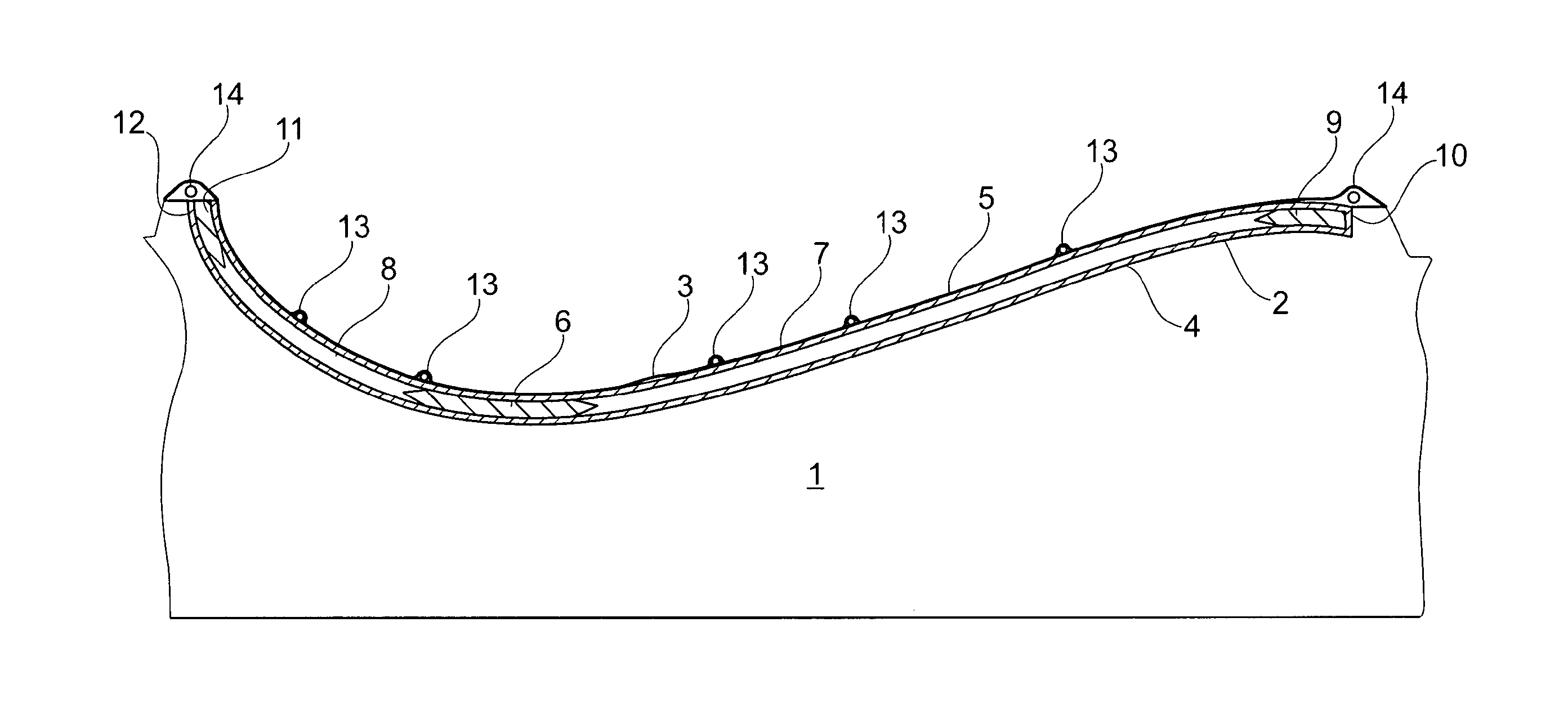
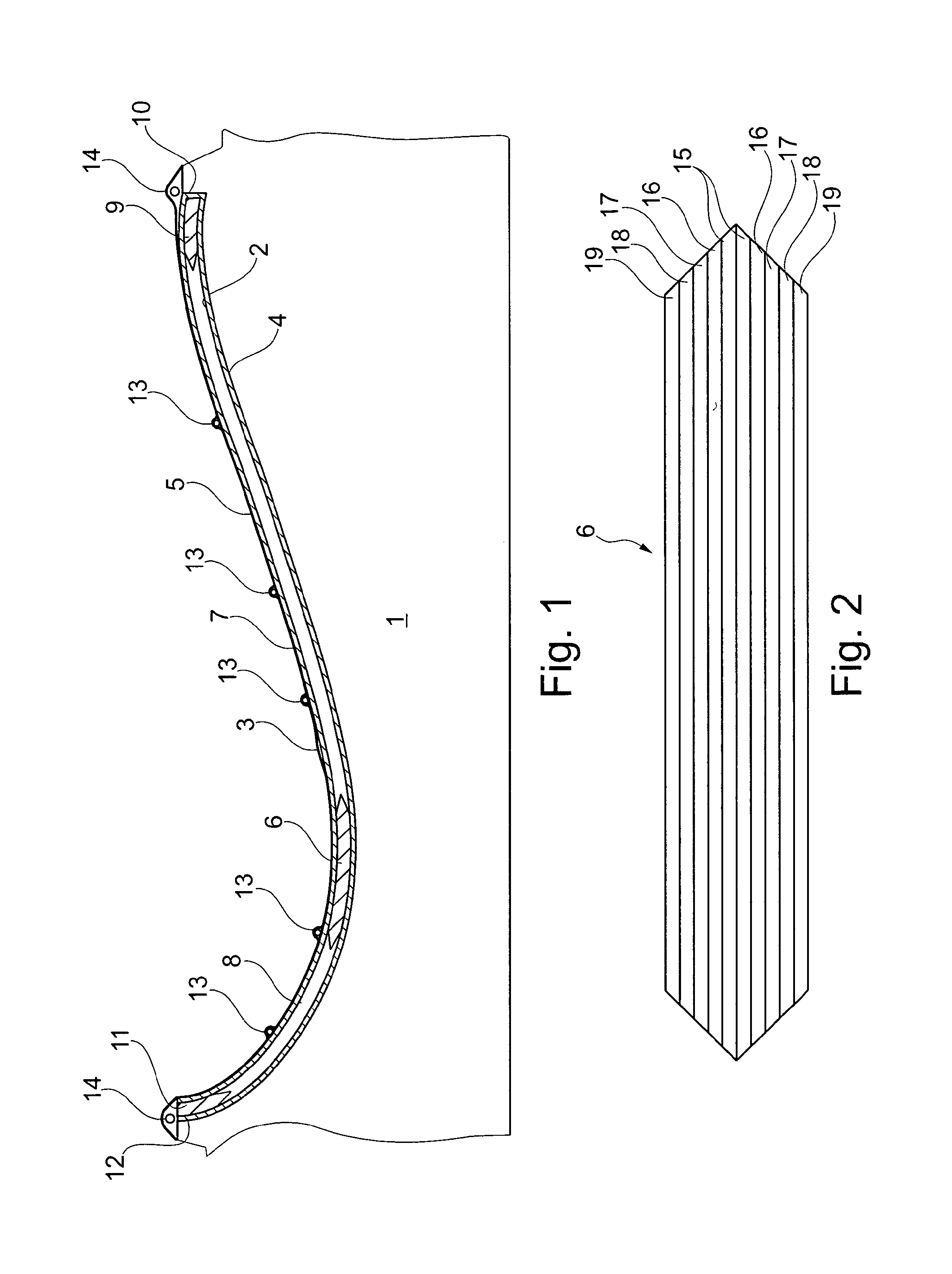
[0066]FIG. 1 is a cross-sectional view through an embodiment of a first mould part 1 for use in VARTM process. The first mould part 1 is a rigid mould part and has an upwardly facing forming surface 2. A second mould part 3 being a so-called vacuum bag is sealed to the first mould part 1, whereby a mould cavity is formed between the first mould part 1 and the vacuum bag 3. A number of fibre layers, core parts and reinforcement sections are placed in the mould cavity, said parts being included in a finished wind turbine blade shell part, in the present example the shell half defining the pressure side of the blade.

[0067]The blade shell part comprises one or more lower fibre layers 4 impregnated with resin and optionally coated with gelcoat defining the exterior surface of the shell part, and one or more upper fibre layers 5 impregnated with resin and defining the interior surface of the shell part. The upper and lower fibre layers 5, 4 may be formed of mats comprising any fibre mater...


PUM

PropertyMeasurementUnit
sizeaaaaaaaaaa
volumeaaaaaaaaaa
structureaaaaaaaaaa

Abstract

Wind turbine blade has a longitudinal direction and includes a shell structure made of a fibre-reinforced polymer material including a polymer matrix and reinforcement material comprising a plurality of carbon fibre layers embedded in the polymer matrix. At least a portion of the shell structure is formed of a laminate 6 comprising at least one metal filament layer 15, 18 comprising metal filaments and being sandwiched between two carbon fibre layers 16,16;17,18 comprising carbon fibres only. The carbon fibre layers are arranged contiguously with the metal filament layer.

Description

TECHNICAL FIELD[0001]The present invention relates to a wind turbine blade having a longitudinal direction and including a shell structure made of a fibre-reinforced polymer material including a polymer matrix and reinforcement material comprising a plurality of carbon fibre layers embedded in the polymer matrix.[0002]The invention further relates to a method of manufacturing a shell structure part of a wind turbine blade, the shell structure part being made of a fibre-reinforced polymer material including a polymer matrix and a fibre-reinforcement material comprising a plurality of carbon fibre layers embedded in the polymer matrix.BACKGROUND ART[0003]Vacuum infusion or VARTM (vacuum assisted resin transfer moulding) is one method, which is typically employed for manufacturing composite structures, such as wind turbine blades comprising a fibre-reinforced matrix material. During the manufacturing process, liquid polymer, also called resin, is filled into a mould cavity, in which fi...

Claims


Application Information

Patent Timeline
Patent Type & Authority Applications(United States)
IPC IPC(8): F01D5/28B29C70/02
CPCF01D5/282B29C70/021B29C70/547B29L2031/082B32B15/14B32B27/306B32B27/36B32B27/38B32B2262/103F03D1/065F03D1/0675F05B2280/10F05B2280/2006F05B2280/6013Y02E10/721Y02E10/72B32B27/08B32B2262/106B32B2603/00F05B2280/6003B29L2031/085Y02P70/50F05D2300/614F05D2300/603F05D2300/6034
Inventor DAHL, MARTINMORTENSEN, BJARNE KRABOLESEN, MORTEN
Owner LM WIND POWER AS
Why Eureka
Try Eureka