Tillage system

a technology of tillage system and tillage hole, which is applied in the field of tillage system, can solve the problems of limiting the ability of water to enter the field, unfavorable water run-off, and unfavorable plant stock and weed growth, so as to achieve the effect of reducing the amount of water runoff, and ensuring the appearance of tilled fields

Inactive Publication Date: 2014-05-08
NANCE JOHN D
View PDF5 Cites 13 Cited by
  • Summary
  • Abstract
  • Description
  • Claims
  • Application Information

AI Technical Summary

Benefits of technology

[0013]The present invention provides an add-on tillage system that can be added-on to existing agricultural devices and tools for tilling. The present invention provides a tillage add-on device adapted to till a field in spring prior to planting and in fall after harvesting farm crops for primary tillage. The system of this invention includes a plurality of spaced first deep tilling tines that plough the field deep along planting rows. A plurality of spaced rows of shallow tilling tines positioned in front of and mostly behind the deep tilling tines in the moving direction of the tiller smoothen the ground adjacent to the deep tilled location and clear the debris on the land segments between the deep tilled planting rows. This creates a field that appears tilled, rather than a field which, despite having been deep tilled, retains unsightly plant stocks and weed residue between the deep tilled locations. The last row of shallow tilling coulter is always provided that has a ruffled disk pushes debris such as plant stocks into the ground, thereby mixing and anchoring tilled soil between the deep-tilled groves and preventing water run-off and consequent soil erosion. A third set of tools has a series of harrows, cage rollers or packer wheels may be used behind the shallow tilling ruffled disks to smoothen the soil surface.
[0014]In a first embodiment, the add-on tillage system includes a tilling unit having a common tool bar having attached thereto a first set of a plurality of tilling tines or coulters adapted to produce deep grooves in a tilled field. Means are provided for adjusting spacing between the tines or coulters, tilling tines or coulters up and down as a group being loaded by spring force, compressed air pistons or hydraulically actuated rams. A first mount is adapted to receive a tongue with hydraulic operations for mounting to a tractor. A second mount is adapted to receive a tongue with hydraulic mount to an agricultural device adapted to be pulled by the tractor. The add-on tillage system tills surface soil for a clean appearance, providing improved rain / irrigation water absorption, eliminating water run-off and erosion.
[0015]The tillage system has a tool bar that carries a plurality of deep tilling tines with inserted hardened steel projections adapted to till the ground along a plurality of planting rows. Due to the large diameter of these deep-tilling tines, the depth of till may be adjusted from about 5 inches to 12 inches for fall tilling and from 5 to 8 inches for spring tilling. Such an adjustment is easily made by changing the location of an individual attachment bar loaded by spring, air pressure or a hydraulic ram, which connects the deep tilling cutters to the tool bar. This first set of deep-tilling tines may be driven at a tilling ground speed selected by the operator. When a deep tilling tine comes across a hard object such as rock, the loading mechanism yields, thereby preventing damage to the deep tilling tines. The deep tilling tines unearth weeds and bring to the top of the soil any plant roots present there within. As a result of this deep tilling, deep grooves are formed in the field. These grooves are bound by two mounds of soil, one mound being located to either side of the deep groove. The deep tilling tines may be made with a number of structural configurations including toothed tines with lateral and radial extensions, three dimensionally formed ruffled coulters and other geometric shapes all designed to deep till to a depth of 5 to 12 inches. If deeper depth is required for different soil types, the diameter of the deep tillage tine will be increased. Unless disturbed, the land segments between the deep grooves would remain essentially untilled and exhibit an unsightly appearance. A conventional tilling system does not have these shallow tilling tines or coulters such as that disclosed in U.S. Pat. No. 7,575,066 to Bauer strictly produces the tilling of deep grooves at the plant rows. Irrigation of the field occasioned by rain or artificial irrigation causes water to collect within the deep grooves. The deep grooves have limited volume, which limits their ability to absorb water into the field. Moreover, the mounds formed to either side of the grooves typically contain high quality topsoil, which tends to be washed off, carrying fertilizer that was previously applied, and producing soil erosion. The ability of water to be absorbed in the untilled portion of the field between the deep tilled grooves is very limited and most of the water supplied by rain or artificial irrigation runs off from the field due to soil compaction without benefiting the planted crop.

Problems solved by technology

This creates a field that appears tilled, rather than a field which, despite having been deep tilled, retains unsightly plant stocks and weed residue between the deep tilled locations.
Unless disturbed, the land segments between the deep grooves would remain essentially untilled and exhibit an unsightly appearance.
The deep grooves have limited volume, which limits their ability to absorb water into the field.
Moreover, the mounds formed to either side of the grooves typically contain high quality topsoil, which tends to be washed off, carrying fertilizer that was previously applied, and producing soil erosion.
The ability of water to be absorbed in the untilled portion of the field between the deep tilled grooves is very limited and most of the water supplied by rain or artificial irrigation runs off from the field due to soil compaction without benefiting the planted crop.

Method used


Image

  • Tillage system
  • Tillage system
  • Tillage system

Examples


Embodiment Construction

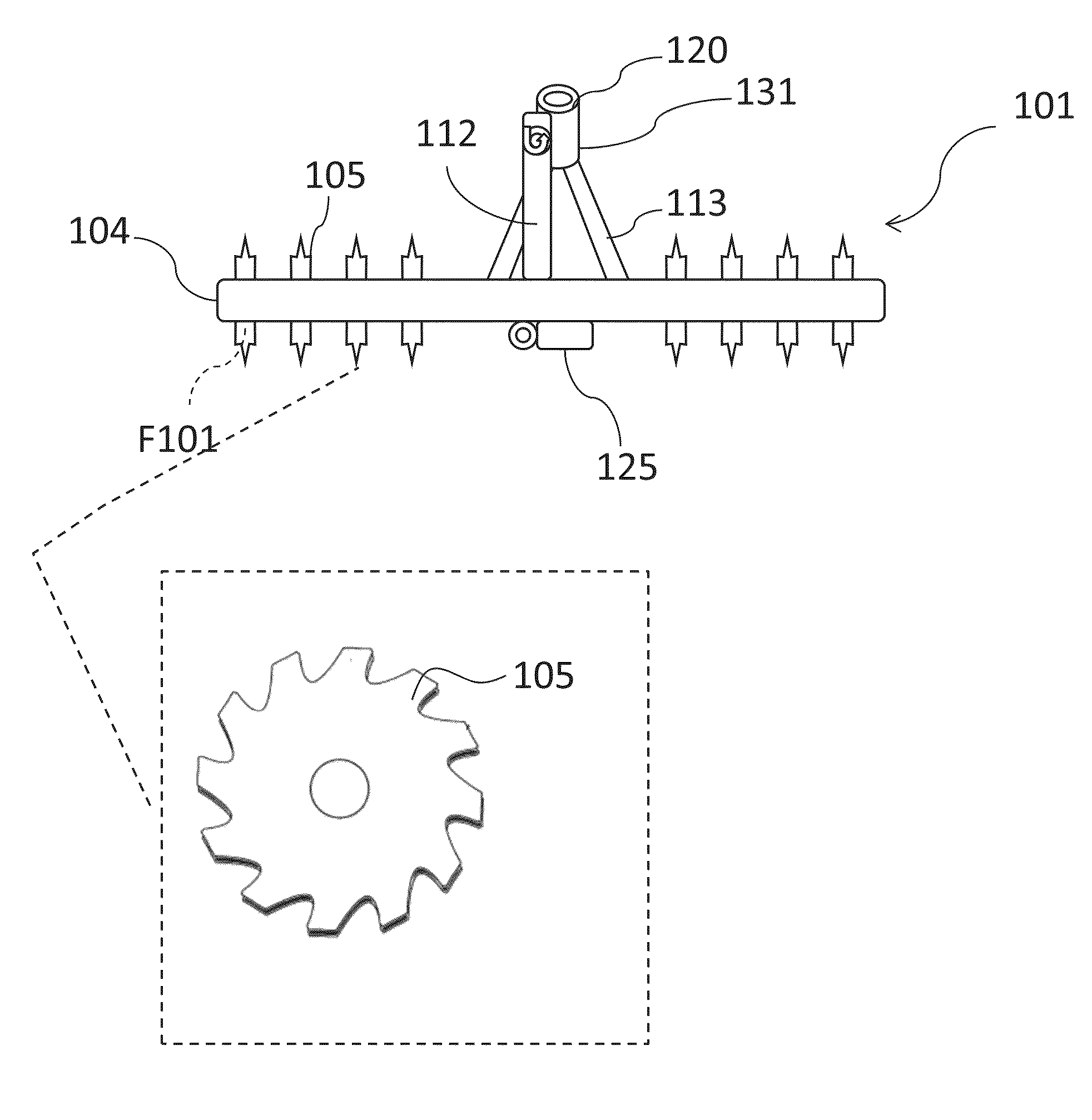
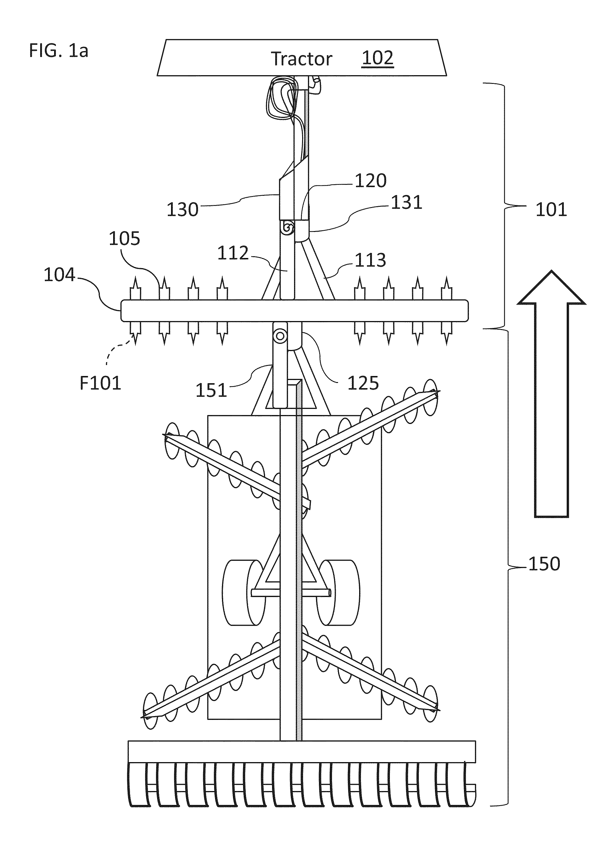
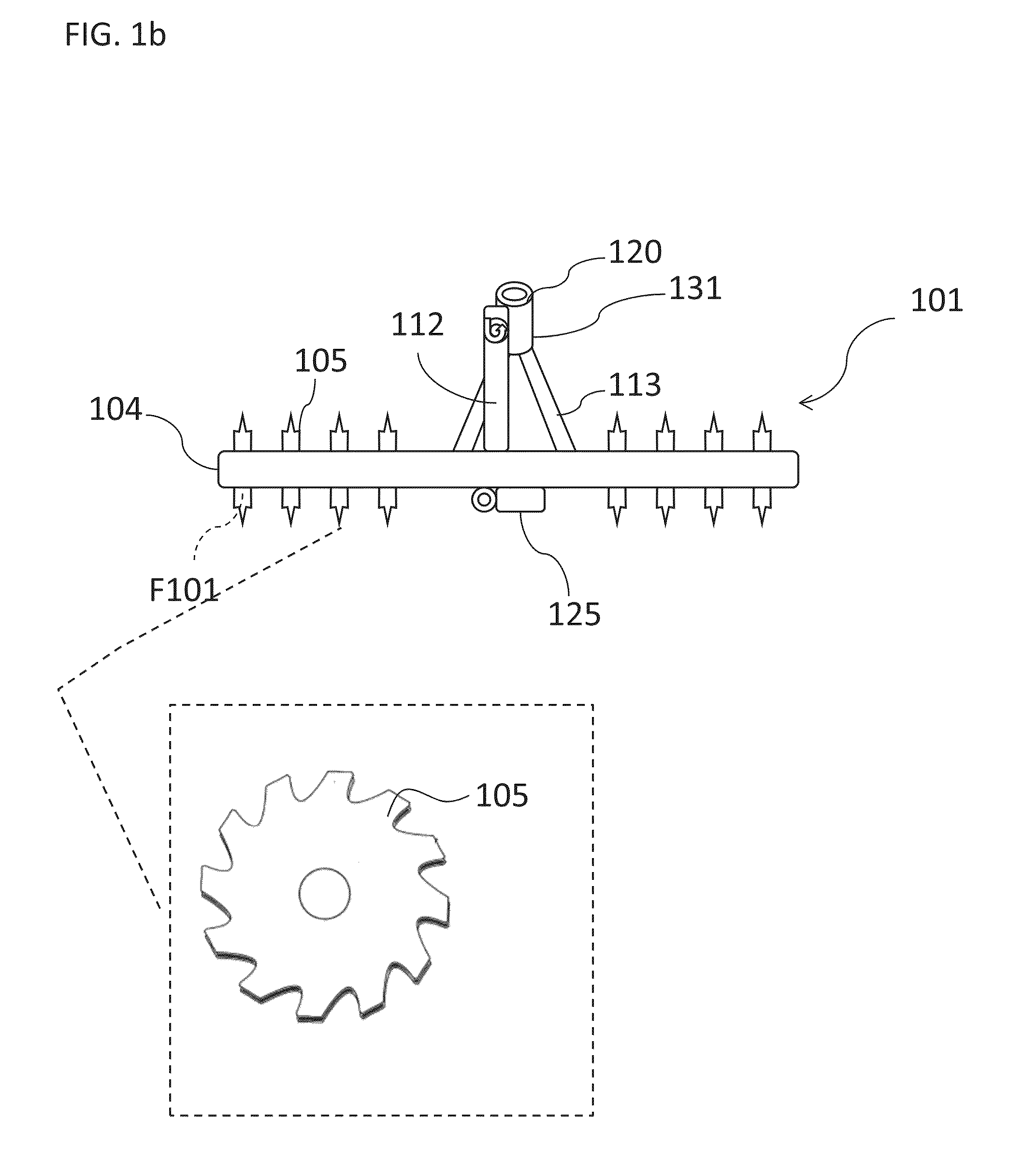
[0054]This invention relates to a tilling system adapted to be added-on to existing agricultural devices, including vertical tilling, vertical combination, horizontal and conventional tilling and fertilizer machinery. The add-on tilling system generally comprises a tool bar that carries a plurality of tillage tools, preferably comprising deep tilling tines, each being adjustable in spacing and adapted to be lowered or raised above the ground. The tool frame preferably carries a row deep tilling tine, however it is noted that a plethora of different tilling coulters can be utilized. All of the deep tilling tines and shallow tilling coulters run at the ground speed of the tillage system selected by the tillage system operator.

[0055]The subject tilling system provides the ability to readily convert agricultural tools or devices to include deep tillage by adding the subject tilling system / unit to the existing separate agricultural device. For example, the following agricultural devices ...


PUM


Abstract

An add-on tillage system is adapted to be mounted on an agricultural device to enhance tilling ability. The add-on tillage system includes a tilling unit with a common tool bar having attached thereto a first set of a plurality of tilling tines or coulters adapted to produce deep grooves in a tilled field. Means are provided for adjusting spacing between the tines or coulters, tilling tines or coulters up and down as a group being loaded by spring force, compressed air pistons or hydraulically actuated rams. A first mount is adapted to receive a tongue with hydraulic operations for mounting to a tractor. A second mount is adapted to receive a tongue with hydraulic mount to an agricultural device adapted to be pulled by the tractor. The add-on tillage system tills surface soil for a clean appearance, providing improved rain / irrigation water absorption, eliminating water run-off and erosion.

Description

[0001]This is a Continuation-In-Part of U.S. application Ser. No. 12 / 658,486 filed Feb. 8, 2010 for “Tillage System”, the disclosure of which is hereby incorporated in its entirety by reference thereto.BACKGROUND OF THE INVENTION[0002]1. Field of the Invention[0003]The present invention relates to a tillage system used by farmers to till a field in spring prior to planting and in fall after harvesting farm crops; and, more particularly to a tillage system used to produce deep tilled rows and shallow tilled regions therebetween, leaving behind a smooth clean-tilled field that conserves water and soil fertility without excessive soil erosion.[0004]2. Description of the Prior Art[0005]Many patents address issues related to tilling a farm field. Several of the tillage systems are designed to deep-till a field. Such deep-tilling causes top soil loss due to soil erosion. In addition, deep-tilling degrades field fertility more and more each year. Run-off of soil and fertilizer tends to pol...

Claims


Application Information

Patent Timeline
Patent Type & Authority Applications(United States)
IPC IPC(8): A01B49/02A01B7/00A01B49/06
CPCA01B49/027A01B7/00A01B49/06A01B23/06A01B49/02
Inventor NANCE, JOHN D.
Owner NANCE JOHN D
Why Eureka
Try Eureka