Electric power tool

a technology of electric power tools and impulse tools, which is applied in the direction of power driven tools, wrenches, screwdrivers, etc., can solve the problems of compact tool construction compared to the prior art arrangement, and achieve the effects of improving connection, ensuring safety, and ensuring safety

Active Publication Date: 2014-05-08
ATLAS COPCO INDAL TECHN AB
View PDF41 Cites 3 Cited by
  • Summary
  • Abstract
  • Description
  • Claims
  • Application Information

AI Technical Summary

Benefits of technology

[0006]An object of the invention is to provide an electric torque delivering impulse tool, which is more durable and more efficient than a conventional torque delivering impulse tool. A specific object of the invention is to provide an improved connection between the motor and the pulse unit, in order to achieve a higher efficiency, a reduced weight and / or a prolonged life time for the tool.

Problems solved by technology

Further, the construction of the tool will be more compact with respect to that of prior art arrangements.

Method used


Image

  • Electric power tool
  • Electric power tool
  • Electric power tool

Examples


first embodiment

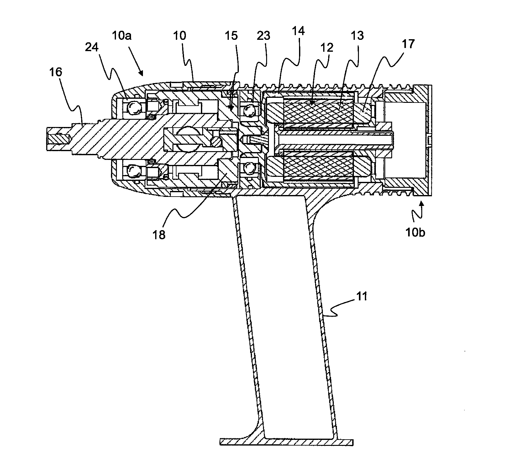
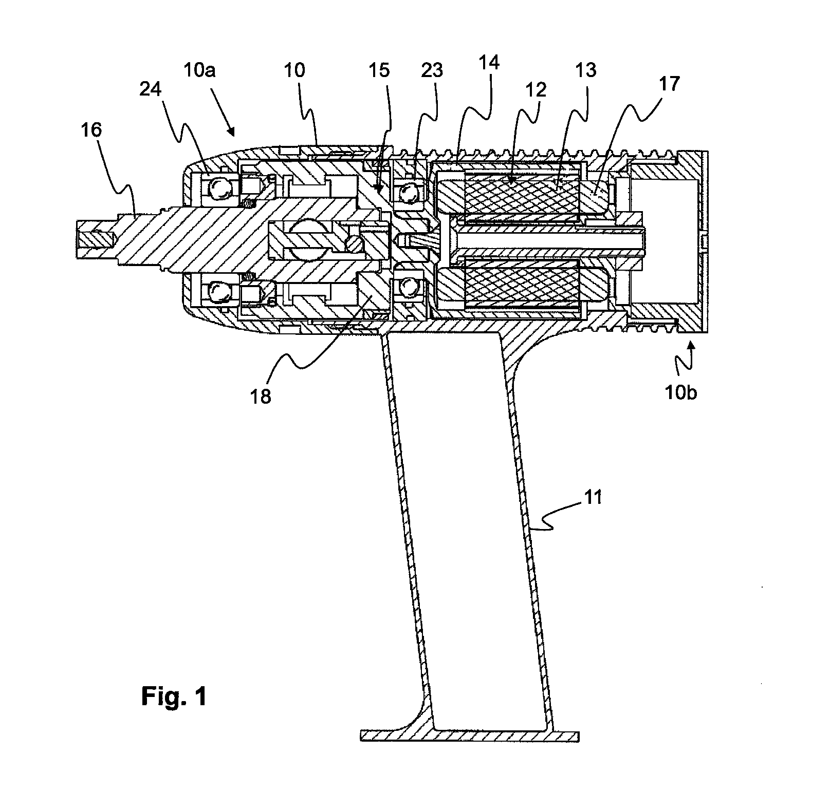
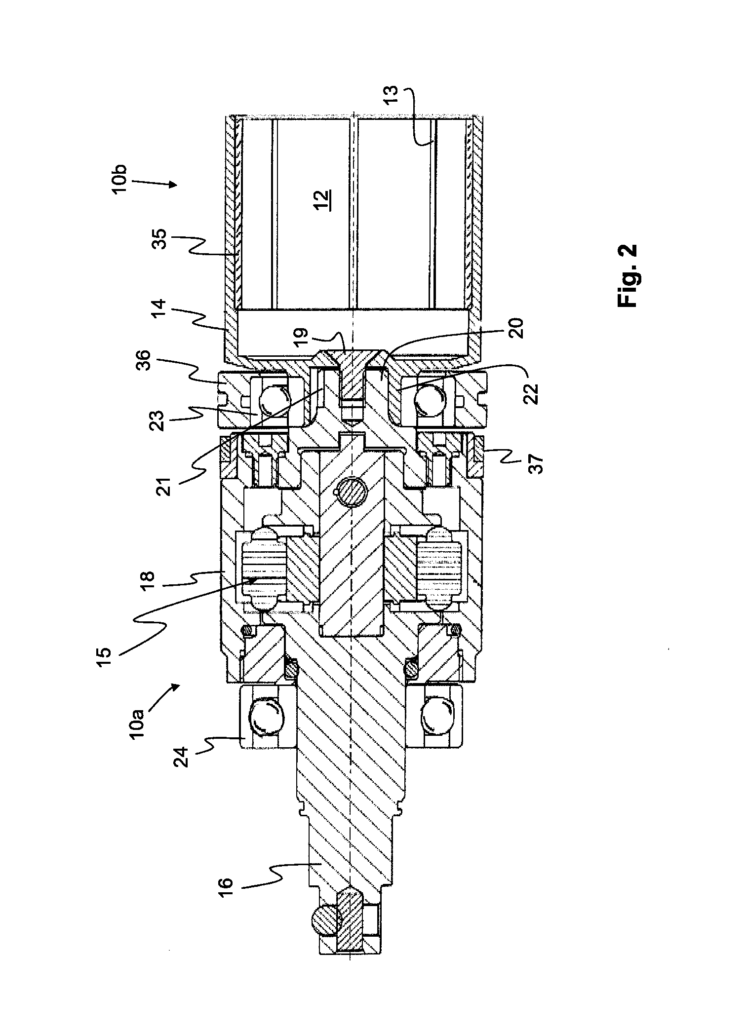
[0022]A detailed view of the motor 12 and the pulse unit 15 of the invention is shown in FIG. 2. An advantage of the invention is that the motor rotor 14 and the pulse unit 15 are intimately assembled to form one single structure, such that there is no gap or play between the interconnected parts. This may be achieved in different manners whereof two possible embodiments are shown in FIGS. 2 and 3, respectively.

[0023]In the first embodiment, e.g. the embodiment shown in FIGS. 1 and 2, the stator 13 is arranged inside the rotor 14. Typically the stator 13 comprises a conventional electrical winding 17. The rotor 14 comprises a permanent magnet 35, which is located on the inside of the rotor 14. In a not shown alternative embodiment of the invention the rotor is arranged inside the stator, instead of outside it.

[0024]In the embodiment shown in FIGS. 1 and 2 the rotor 14 is connected to a cylindrical inertia drive member 18 of the pulse unit 15 via a male and female connection part 20 ...

second embodiment

[0033]In order to prohibit mutual movement in the opposite axial direction, i.e. in the separating direction, a block 34 in the form of a solid plate has been provided. The block 34 restricts the movement of the splined coupling part 32 of the rotor 14 away from the splined coupling part 39 of the inertia drive member 18. The block 34 is fastened to a solid portion of the inertia drive member 18 by means of at least three screws 38. This arrangement provides a very solid connection between the rotor 14 and the inertia drive member 18 in both the axial and the radial direction. No central bearing, arranged around the connection of the rotor 14 and the inertia drive member 18, is arranged in this

[0034]In the second embodiment a front bearing 24 is arranged on the output shaft 16, in the same manner as in the first embodiment. Likewise, the front bearing 24 stabilises the output shaft 16 in both the axial and radial direction. In addition it stabilises the inertia drive member 18 in th...


PUM


Abstract

An electric torque delivering impulse tool includes a housing with a front end and a back end, an electric torque delivering motor with a rotor that is arranged to rotate with respect to a stator, an output shaft arranged at the front end of the housing, and a pulse unit intermittently coupling the motor to the output shaft, wherein the pulse unit includes an inertia drive member that is connected to the rotor. The rotor and the inertia drive member are rigidly assembled to each other without play so as to form one integrated rotatable structure which is mounted as one single unit inside the housing.

Description

[0001]The invention relates to an electric torque delivering impulse tool, such as e.g. a screw machine. In particular the invention relates to a tool with an interconnected electric motor and a torque impulse generating pulse unit.[0002]In a conventional torque delivering impulse tool the motor and the torque impulse generating pulse unit are mounted with individually bearings and the motor and the pulse unit are interconnected by means of e.g. a hexagonal or quadratic male and female connection part, which are interconnected such that a play or allowance by necessity exists between them. The allowance between the interconnected parts is inevitable for assembly with respect to manufacturing tolerances of the parts.[0003]A problem inherent in this conventional arrangement is that an increasing gap is formed between e.g. the hexagonal male and female connection parts. This gap will increase due to the joint work of the motor, on the one hand, and the partly opposed work of the pulse ...

Claims


Application Information

Patent Timeline
Patent Type & Authority Applications(United States)
IPC IPC(8): B25B21/02
CPCB25B21/02B25F5/00B25B21/00B25B23/0007B25B23/1475
Inventor KVIBERG, ERIK MARKUS PEDERNELSON, ANDERS URBAN
Owner ATLAS COPCO INDAL TECHN AB
Why Eureka
Try Eureka