Rotational angle measurement apparatus, control apparatus, and rotation-machine system

a technology of rotational angle measurement and control apparatus, which is applied in the direction of motor/generator/converter stopper, electric device, engine-driven generator, etc., can solve the problems of difficult magnetic sensor to detect the angle correctly, and difficulty in accurately measuring the angle of magnetic field, etc., and achieve the effect of sufficient accuracy

Active Publication Date: 2014-05-08
HITACHI ASTEMO LTD
View PDF2 Cites 16 Cited by
  • Summary
  • Abstract
  • Description
  • Claims
  • Application Information

AI Technical Summary

Benefits of technology

[0023]According to the present invention, it is possible to measure a magnetic-field angle or a rotational angle with sufficient accuracy, in the configuration in which a non-magne

Problems solved by technology

In a rotational angle sensor in the past, in cases where a non-magnetic conductor (electrical conductor) is arranged between a magnetic flux generator installed in a rotatable body and a magnetic sensor, when the rotatable body rotates or moves at high speed, there occur

Method used


Image

  • Rotational angle measurement apparatus, control apparatus, and rotation-machine system
  • Rotational angle measurement apparatus, control apparatus, and rotation-machine system
  • Rotational angle measurement apparatus, control apparatus, and rotation-machine system

Examples


example 1

[0052]As an example of a magnetic sensor of the magnetic-field angle measurement type, a magnetic sensor which employs a GMR element is described hereinafter.

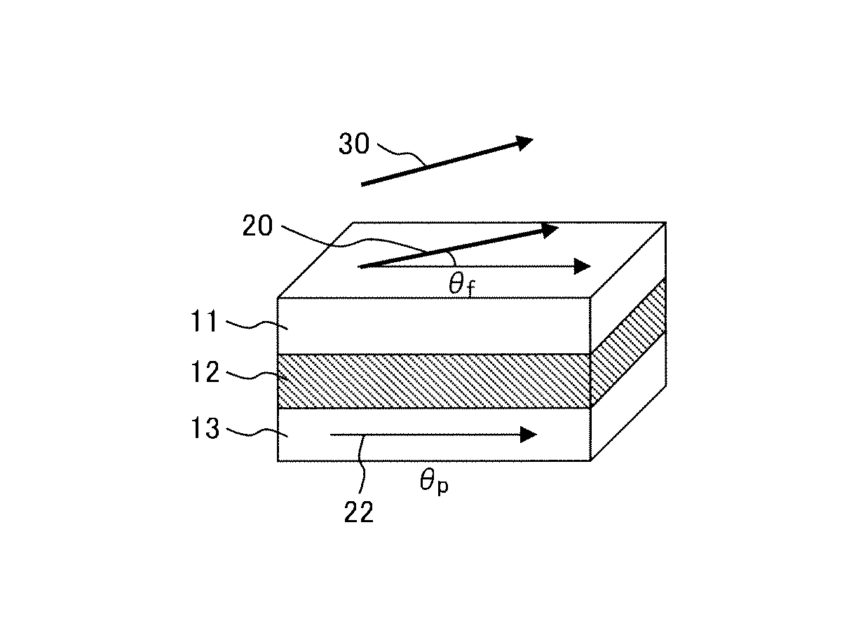
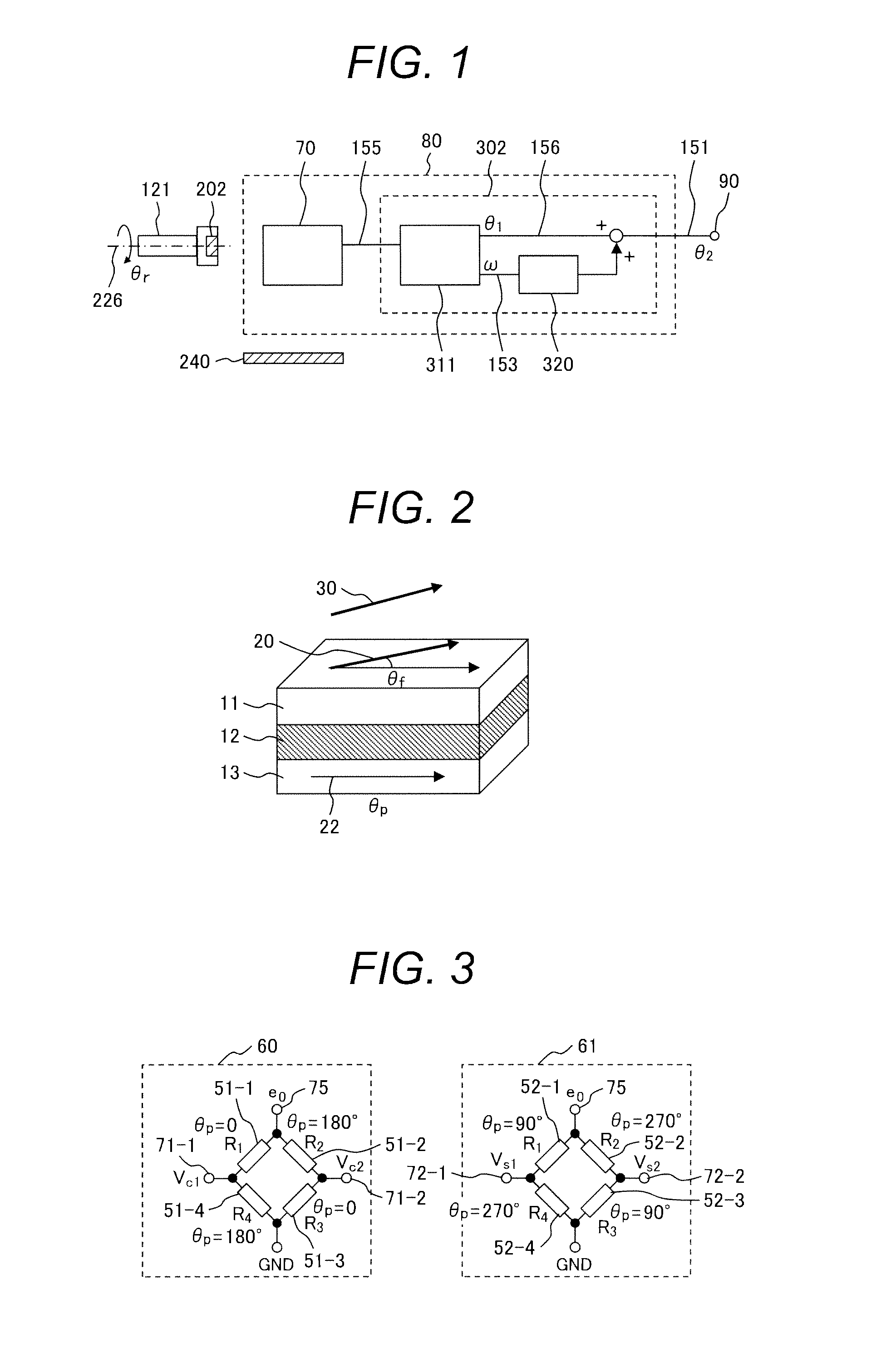
[0053]FIG. 2 illustrates a basic configuration of a GMR element. The GMR element is configured with a first magnetic layer (fixed magnetic layer or pinned magnetic layer) 13, a second magnetic layer (free magnetic layer) 11, and a non-magnetic layer (spacer layer) 12 which is laminated between both magnetic layers. When an external magnetic field is applied to the GMR element, the angle of magnetization 22 of the fixed magnetic layer 13 does not change and is fixed; however, the angle of magnetization 20 of the free magnetic layer 11 changes corresponding to the angle of the external magnetic field 30.

[0054]In the present specification, the angle of magnetization 22 of the fixed magnetic layer 13 is called a pin angle and expressed as θp.

[0055]When a voltage is applied to both ends of the GMR element, an electric current corres...

example 2

[0118]Example 2 according to the present invention is described with reference to FIG. 9. The same reference symbol is attached in the same configuration as in the previous example, and the explanation thereof is omitted.

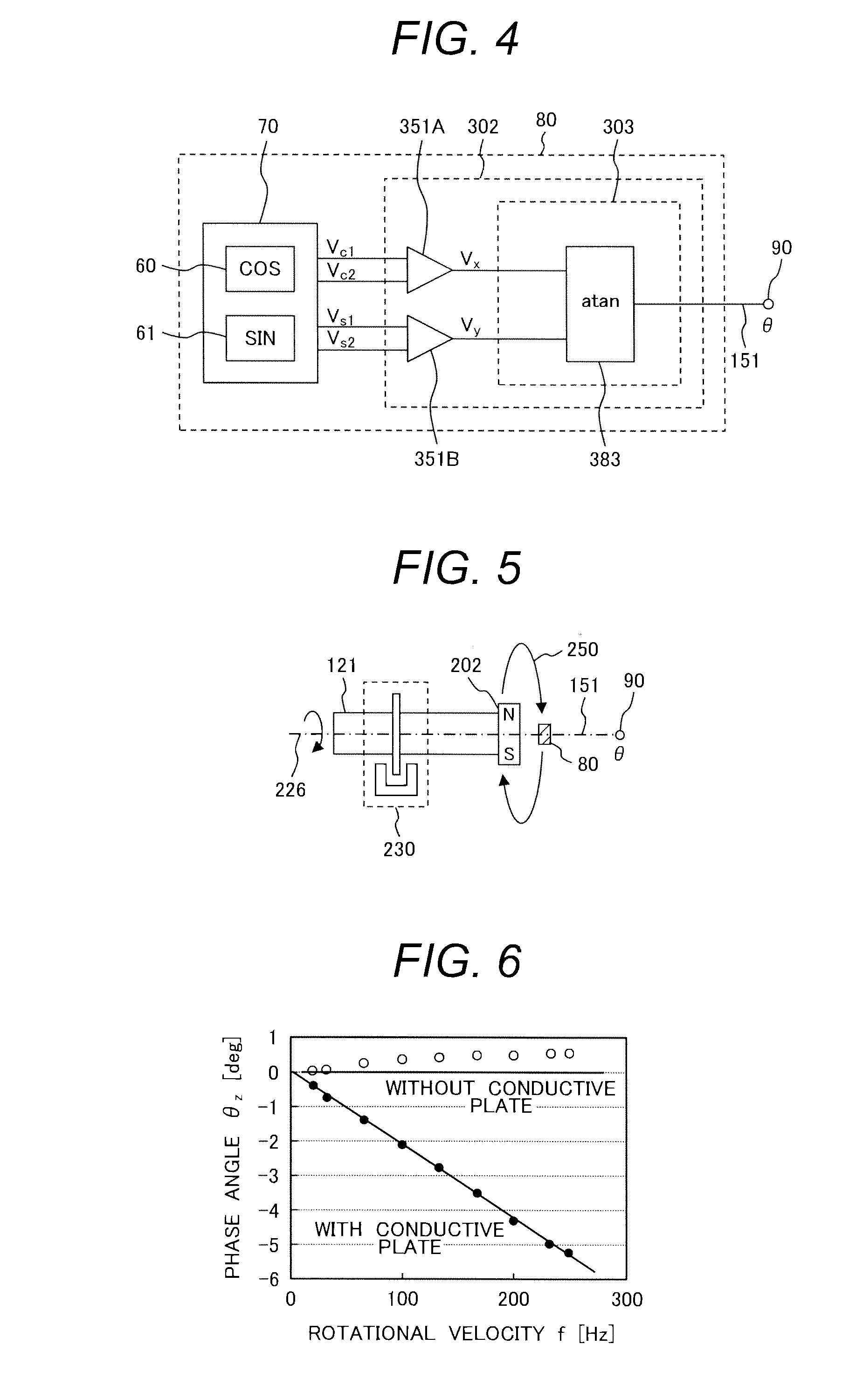
[0119]In the present example, the rotational angle measurement apparatus 80 is provided with a rotational-velocity signal input terminal 94. By inputting a signal corresponding to the rotational velocity of the rotatable body 121 from the rotational-velocity signal input terminal 94, the rotational angle measurement apparatus 80 calculates the correction value corresponding to the rotational velocity 153 (ω) in the correction unit 320, corrects the simple angle signal 156 (θ1) with the use of the correction value, and outputs the corrected angle signal 151 (θ2) to the angle-output terminal 90.

[0120]In the present example, it is not necessary to calculate the rotational velocity 153 (ω); therefore, there is an advantage that the configuration of the detection unit 30...

example 3

[0125]Example 3 according to the present invention is described with reference to FIG. 10. The same reference symbol is attached in the same configuration as in the previous examples, and the explanation thereof is omitted.

[0126]In addition to the configuration illustrated in FIG. 1, a correction-function configuration means 95 is provided in the present example.

[0127]As described above, the function form which expresses the dependence of the discrepancy of the angle origin on the rotational velocity is dependent on the material, shape, and arrangement location of a conductor, at least. Therefore, a suitable function form of the correction function is also dependent on the material, shape, and arrangement location of the conductor.

[0128]In the rotational angle measurement apparatus 80 according to the present example, the correction-function configuration means 95 is provided; accordingly, it is possible to change the function form of the correction function. Therefore, it is possib...


PUM


Abstract

Rotational angle measurement apparatus measuring magnetic-field angle or rotational angle with sufficient accuracy wherein a non-magnetic conductor is arranged in the vicinity of the magnetic flux generator or the magnetic sensor, even when the magnetic flux generator rotates at high speed. The rotational angle measurement apparatus is configured with a magnetic sensor 70 which responds to a magnetic-field angle and a detection unit 302 which inputs an output of the magnetic sensor. The rotational angle measurement apparatus is employed with a rotatable body 121 provided with a magnetic flux generator 202. The output of the magnetic sensor is a raw-angle signal set 155 corresponding to the magnetic-field angle. The detection unit outputs a corrected angle after a non-magnetic conductor in the vicinity of the magnetic sensor is corrected, using a correction value outputted by a correction function with rotational velocity of the rotatable body as an argument.

Description

TECHNICAL FIELD[0001]The present invention relates to a rotational angle measurement apparatus with a magnetic sensor, a rotation machine, and a rotation-machine system, and also relates to a control apparatus for controlling a rotation machine, etc., by processing a magnetic sensor signal.BACKGROUND ART[0002]A magnetic flux generator (hereinafter called a “sensor magnet”) is installed in a rotatable body, and a magnetic sensor is installed in a location within the reach of magnetic flux generated by the magnetic flux generator. It is known that, when the rotatable body rotates, the angle of the magnetic flux generated by the sensor magnet also rotates, and that the rotational position (rotational angle) of the rotatable body can be measured by detecting the angle of the magnetic flux through the use of a magnetic sensor.[0003]Here, the magnetic sensor is broadly divided into two groups: a magnetic-field-intensity-measurement sensor which outputs a signal corresponding to the intens...

Claims


Application Information

Patent Timeline
IPC IPC(8): G01B7/30G01R33/09H02P6/00G01R33/00
CPCG01B7/30H02P6/00G01R33/093G01R33/0047G01D5/145G01D5/24476H02P6/16B60L3/12B60L2220/14B60L2240/421B60L50/61B60L50/16B60L58/12Y02T10/62Y02T10/64Y02T10/70Y02T10/7072B62D5/04
Inventor SUZUKI, MUTSUMI
Owner HITACHI ASTEMO LTD
Why Eureka
Try Eureka