Power relay assembly driving apparatus and driving method thereof

a technology of power relays and driving apparatuses, which is applied in the direction of propulsion by batteries/cells, electric devices, transportation and packaging, etc., can solve the problems of high voltage relays with complicated mechanical structures, high cost of components, and increased power relay assembly weight, so as to reduce the entire weight of the switching unit, enhance fuel efficiency of the vehicle, and prevent the effect of temperature increase damag

Active Publication Date: 2014-05-08
YURA CORP CO LTD
View PDF0 Cites 7 Cited by
  • Summary
  • Abstract
  • Description
  • Claims
  • Application Information

AI Technical Summary

Benefits of technology

[0006]Therefore, an object of the present invention is to provide a power relay assembly driving apparatus capable of replacing an expensive special gas-charged relay used to prevent occurrence of an arc at a contact of a_relay, by a cheap general relay, under control of a battery management system (BMS) or a main controller, and capable of enhancing fuel efficiency of a vehicle by having a reduced entire weight due to the general relay, and a driving method thereof.
[0007]Another object of the present invention is to provide a power relay assembly driving apparatus capable of preventing damage of a switching unit due to temperature increase, by controlling a current flow according to a temperature sensed by a protection unit, and a driving method thereof.
[0008]Another object of the present invention is to provide a power relay assembly driving apparatus capable of handling a case where a switching unit or a protection unit has broken down using a communication unit, and handling a case where an over-current flows using a current sensing unit, and capable of preventing contact fusion occurring at a contact of a relay when a short circuit has occurred, and a driving method thereof.
[0009]Another object of the present invention is to provide a power relay assembly driving apparatus capable of simplifying arrangement of wires by preventing wire increase due to addition of peripheral devices using a communication unit, and a driving method thereof.
[0010]Another object of the present invention is to provide a power relay assembly driving apparatus capable of minimizing an error resulting from mal-connection of complicated wires by easily controlling a main controller without the complicated wires using a communication unit, and a driving method thereof.

Problems solved by technology

However, such high voltage relay increases the entire weight of the power relay assembly, because it is heavy due to its special gas.
Further, the high voltage relay has a complicated mechanical structure, and has expensive components because the material cost of the components is high.
This may cause the cost of the power relay assembly to be increased.

Method used


Image

  • Power relay assembly driving apparatus and driving method thereof
  • Power relay assembly driving apparatus and driving method thereof
  • Power relay assembly driving apparatus and driving method thereof

Examples


first embodiment

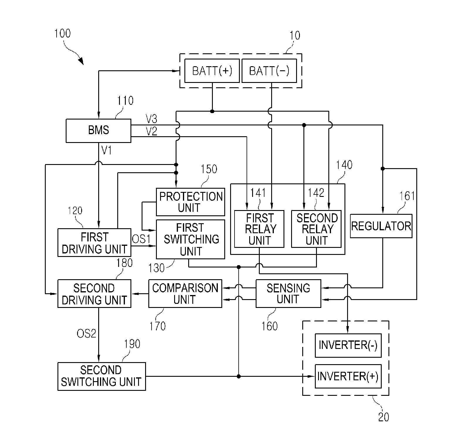
[0039]FIG. 1 is a block diagram of a power relay assembly driving apparatus according to the present invention.

[0040]Referring to FIG. 1, the power relay assembly driving apparatus according to a first embodiment of the present invention 100 is connected between a battery unit 10 and an inverter unit 20, thereby supplying power to the inverter unit 20 from the battery unit 10 or cutting off power supply.

[0041]More specifically, the power relay assembly driving apparatus according to a first embodiment of the present invention 100 comprises a battery management system (BMS) 110, a first driving unit 120, a first switching unit 130, a relay unit 140 including a first relay unit 141 and a second relay unit 142, a protection unit 150, a sensing unit 160, a comparison unit 170, a second driving unit 180, and a second switching unit 190.

[0042]The BMS 110 is electrically-connected to the battery unit 10, thereby maintaining and controlling a state of the battery unit 10. Further, the BMS 1...

second embodiment

[0084]FIG. 5 is a block diagram of a power relay assembly driving apparatus according to the present invention.

[0085]Referring to FIG. 5, the power relay assembly driving apparatus according to a second embodiment of the present invention 200 is connected between a battery unit 10 and an inverter unit 20, and is configured to supply power to the inverter unit 20 from the battery unit 10 or disconnects the power supply. Unlike the power relay assembly driving apparatus according to a first embodiment of the present invention 100, the power relay assembly driving apparatus according to a second embodiment of the present invention 200 does not include the sensing unit 160 and the comparison unit 170.

[0086]More specifically, the power relay assembly driving apparatus according to a second embodiment of the present invention 200 includes a BMS 210, a first driving unit 220, a first switching unit 230, a relay unit 240 having a first relay unit 241 and a second relay unit 242, a protectio...

third embodiment

[0109]FIG. 8 is a block diagram of a power relay assembly driving apparatus according to the present invention.

[0110]Referring to FIG. 8, the power relay assembly driving apparatus according to a second embodiment of the present invention 300 is connected between a battery unit 10 and an inverter unit 20, and is configured to supply power to the inverter unit 20 from the battery unit 10 or disconnects the power supply.

[0111]More specifically, the power relay assembly driving apparatus according to a second embodiment of the present invention 300 includes a BMS 310, a first driving unit 320, a first switching unit 330, a relay unit 340 having a first relay unit 341 and a second relay unit 342, a protection unit 350, a sensing unit 360, a comparison unit 365, a voltage distribution unit 370, a second driving unit 380, and a second switching unit 390.

[0112]The BMS 310 is similar to the BMS 110 of FIG. 1 except that the BMS 310 outputs a fourth voltage (V4) as well as a first voltage (V...


PUM


Abstract

According to one embodiment of the present invention, a power relay assembly driving apparatus comprises: a first relay unit which switches a connection between a first terminal of a battery unit and a first terminal of an inverter unit having a capacitor; a second relay unit which switches a connection between a second terminal of the battery unit and a second terminal of the inverter unit; a first switching unit connected in parallel to the second relay unit between the second terminal of the battery unit and the second terminal of the inverter unit; a second switching unit connected in parallel to the second relay unit between the second terminal of the battery unit and the second terminal of the inverter unit; and a battery management system (BMS) which controls the first relay unit and the first switching unit in order to pre-charge the capacitor with the power of the battery unit, controls the second relay unit in order to normal-charge the capacitor with the power of the battery unit and then controls the first switching unit in order to end the pre-charging of the capacitor, controls the second switching unit upon a power cutoff of the battery unit in order to form an equipotential between the second relay unit and the second terminal of the inverter unit, and controls the second relay unit in order to electrically separate the second terminal of the battery unit and the second terminal of the inverter unit from each other.

Description

TECHNICAL FIELD[0001]The present invention relates to a power relay assembly driving apparatus and a driving method thereof.BACKGROUND ART[0002]Generally, a power relay assembly is a power cutoff apparatus configured to connect and disconnect a power connected to a motor from a battery of an electrical vehicle and a hybrid vehicle using a power control unit (PCU), which is a core component serving as a main gate for supplying a power. Further, the power relay assembly serves as a safety device for completely cutting off power supply in the occurrence of a system error or in a state of repair (maintenance), etc., thereby protecting an electric vehicle / hybrid vehicle.[0003]Such power relay assembly includes a high-voltage relay such as a pre-charging relay (450V, 10 A or more) and a main relay (450V, 100˜150 A or more), a high voltage / large current bus bar for wire connection with a battery / inverter, a terminal, etc. Among such components, a core component is a high voltage relay serv...

Claims


Application Information

Patent Timeline
Patent Type & Authority Applications(United States)
IPC IPC(8): H02J7/00
CPCH02J7/0065B60L3/0023B60L3/04B60L50/51Y02T10/70H02J2207/20
Inventor KIM, HO KYUNGLEE, SANG RYONG
Owner YURA CORP CO LTD
Why Eureka
Try Eureka