
Turbine engine attachment structure

a technology for propellers and engines, applied in the field of aviation, can solve problems such as structural drawbacks, and achieve the effect of optimizing aerodynamic performan

Active Publication Date: 2014-05-15
SN DETUDE & DE CONSTR DE MOTEURS DAVIATION S N E C M A
View PDF14 Cites 21 Cited by
  • Summary
  • Abstract
  • Description
  • Claims
  • Application Information

AI Technical Summary

Benefits of technology

The invention provides a new way to attach a turbine engine to an aircraft with unducted pusher propellers. The attachment structure modifies the way forces are distributed on the power plant compared to conventional structures, which improves aerodynamic performance. A cradle is used to reduce bending moments on the gas generator. A central longitudinal beam is designed with a wider upstream and narrower downstream section, which smooths the streamlines and reduces the impact on efficiency and propeller noise. Overall, the invention satisfies the specific requirements of aircraft with unducted pusher propellers.

Problems solved by technology

Nevertheless, when the nacelle is to receive a power plant having a single unducted propeller or a power plant having two unducted propellers (also known as an open rotor) presenting considerable weight that is cantilevered out, the attachment structure needs to satisfy specific constraints.
Unfortunately, such a structure is not without drawbacks, in particular because of its large size that generates a large amount of wake from the mast that impinges on the propellers.

Method used


Image

  • Turbine engine attachment structure
  • Turbine engine attachment structure
  • Turbine engine attachment structure

Examples


Embodiment Construction

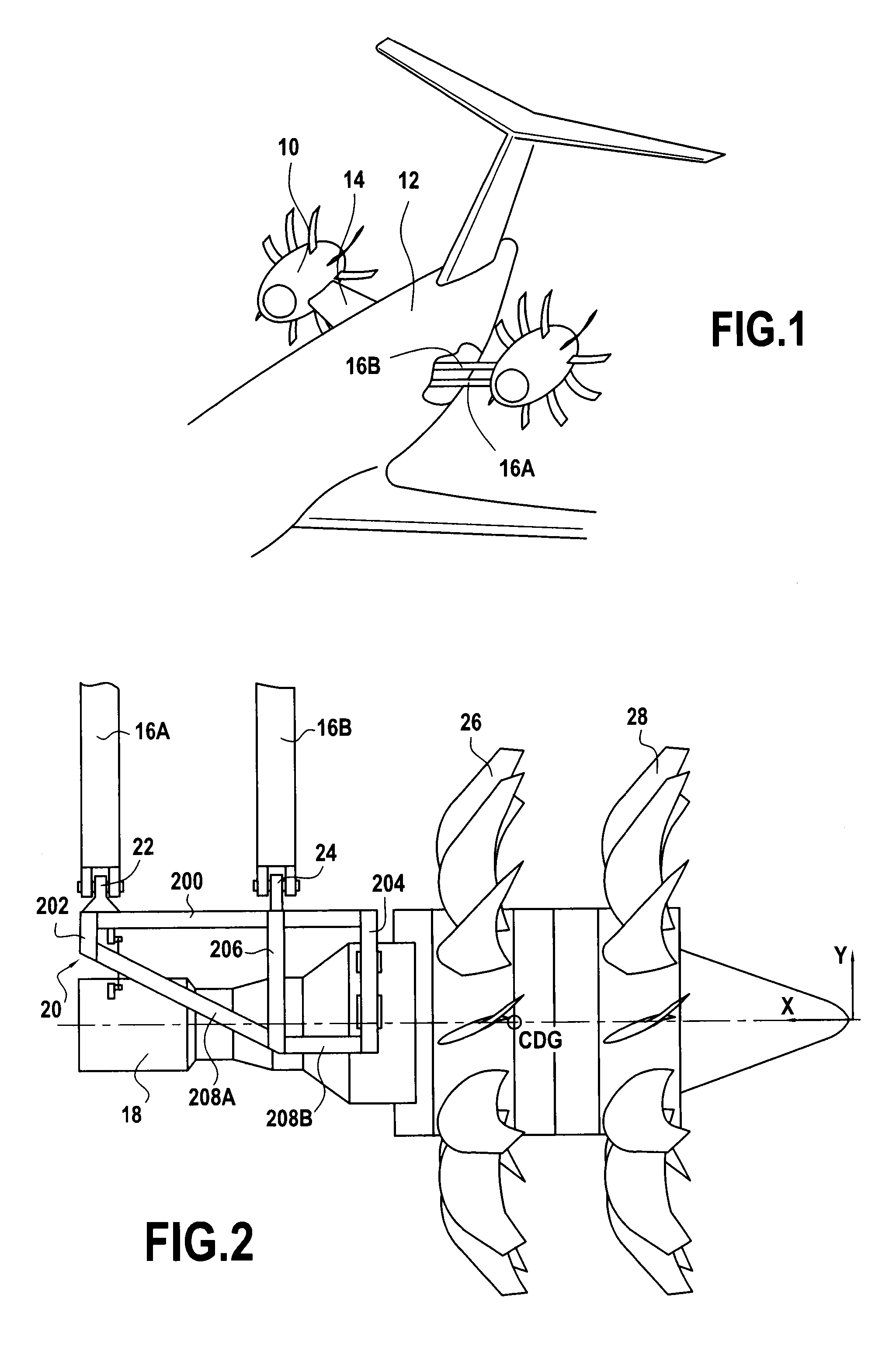
[0021]FIG. 1 is a diagram showing the rear portion of an aircraft having unducted pusher propellers, the nacelle 10 that surrounds and protects the power plant of the aircraft (an assembly forming that which is commonly called a “turboprop”) is suspended from the fuselage 10 by a connection mast or pylon 14 that extends optionally substantially perpendicularly to the surface of the fuselage and that conventionally has two spars 16A, 16B that penetrate into the fuselage and that are fastened at one end to the carrier structure of the aircraft.

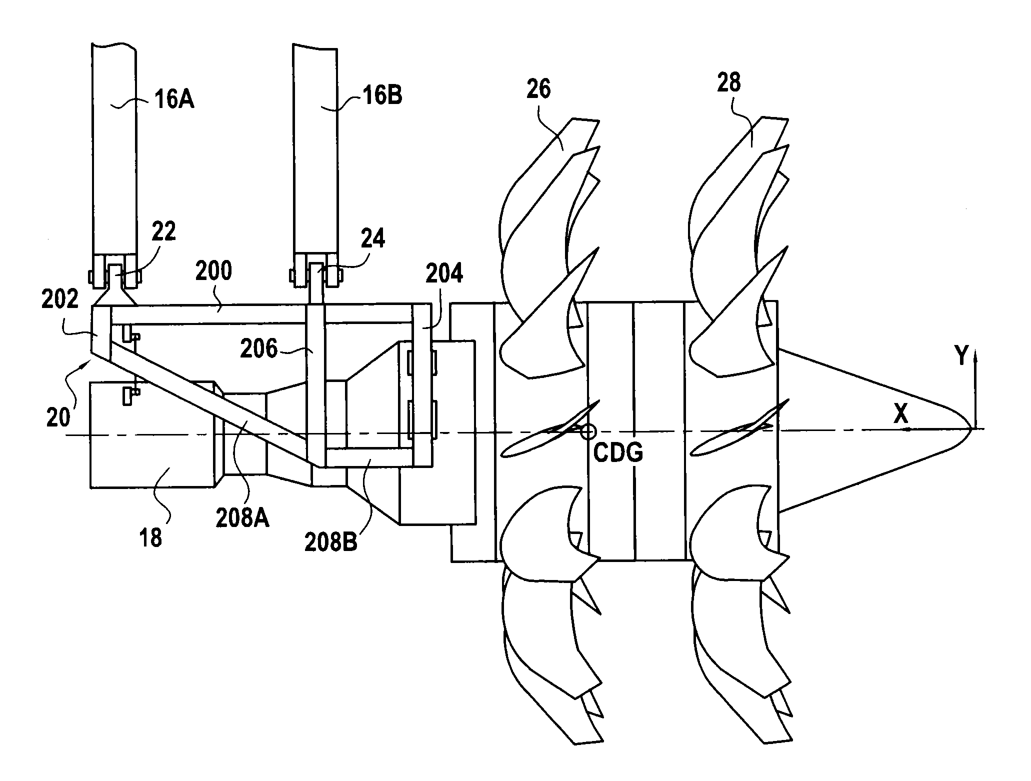
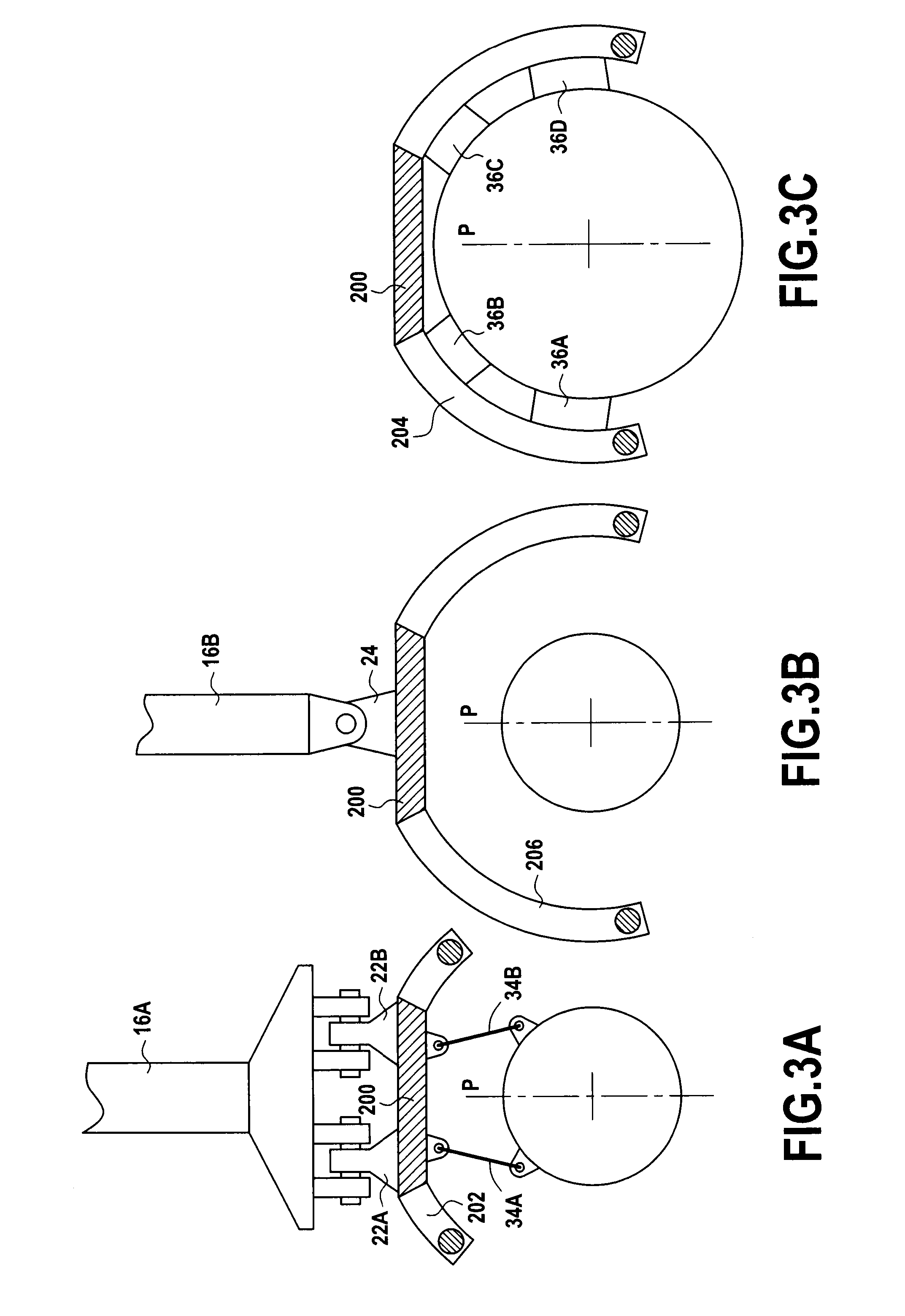
[0022]In the invention, and as shown in FIG. 2, the other ends of these spars, which are for receiving the power plant 18, are fastened to a cradle 20 that is connected to the front and rear spars 16A and 16B via respective first and second fastener means 22 and 24. This cradle attachment structure includes a central longitudinal beam 200 that is secured firstly at its front end to a first frame, or “front” frame 202, arranged in the same plane ...


PUM


Abstract

An attachment structure for attaching a power plant including unducted propellers to a fuselage of an aircraft, the attachment structure being connected by first and second fasteners to respective front and rear spars penetrating into the fuselage and fastened to a carrier structure of the aircraft, and including a central longitudinal beam secured at its front end to a first frame, arranged in the plane of the front spar, that is secured at its rear end to a second rear frame, cantilevered out and arranged upstream from the unducted propellers, and that is secured to a third intermediate frame, arranged in the plane of the rear spar between the first and second frames. The first, second, and third frames are connected together by force-takeup beams, an assembly as constituted in this way forming a cradle for receiving the power plant via a standard attachment.

Description

BACKGROUND OF THE INVENTION[0001]The present invention relates to the field of aviation and it relates more particularly to an attachment structure for unducted pusher propellers.[0002]In conventional manner, aircraft power plants are housed in nacelles that can be arranged at various locations on the aircraft, on or under a wing, or indeed on the rear fuselage, the connection between the power plant and the corresponding portion of the aircraft taking place via an attachment structure of the pylon or mast type, as in patent application EP 0 761 945. Within the power plant, the gas generator forms the upstream portion of the turbine engine.[0003]Nevertheless, when the nacelle is to receive a power plant having a single unducted propeller or a power plant having two unducted propellers (also known as an open rotor) presenting considerable weight that is cantilevered out, the attachment structure needs to satisfy specific constraints. A conventional solution for such attachment is thu...

Claims


Application Information

Patent Timeline
Patent Type & Authority Applications(United States)
IPC IPC(8): B64D27/26
CPCB64D27/26B64D27/14B64D2027/005Y02T50/60Y02T50/40B64D27/402B64D27/026B64D27/40
Inventor CHOUARD, PIERRE-ALAIN JEAN-MARIE PHILIPPE HUGUESVINCENT, THOMAS ALAIN CHRISTIAN
Owner SN DETUDE & DE CONSTR DE MOTEURS DAVIATION S N E C M A
Learn More