Two-Stroke Reciprocating Piston Combustion Engine

a reciprocating piston and combustion engine technology, applied in the field of reciprocating piston combustion engines, can solve the problems of high production cost of heat resistance engine components, slow development of reciprocating internal combustion engines, and unsatisfactory to the modern standard, and achieve the effects of reducing the space inside the crankcase, reducing the gas pressure inside the combustion chamber and expansion cylinder, and quick expansion

Active Publication Date: 2014-05-15
LIU GANG
View PDF2 Cites 7 Cited by
  • Summary
  • Abstract
  • Description
  • Claims
  • Application Information

AI Technical Summary

Benefits of technology

[0011]C. stroking method: when the pistons in the compression cylinder and expansion cylinder are moving from the lowest point to the top most point, the generated gas pressure closes the valve of combustion chamber and the intake valve of the compression cylinder, when the gas pressure inside the compression cylinder is smaller than the spring pressure of the exhaust valve, the gas is retained in the cylinder, and at the same time, because pistons in the compression cylinder and expansion cylinder move up, the space inside the crankcase increases and produces a suction force that closes the exhaust valve of the crankcase and opens the intake exhaust valve, then the gas inside the combustion chamber is sucked through the intake exhaust valve of the combustion chamber, the pipeline and the intake exhaust valve of the crankcase into the crankcase, at the same time, the air outside the engine is also enter through the intake exhaust valve of the crankcase into the crankcase. When the gas pressure inside the compression cylinder is larger than the spring pressure of the compression cylinder valve, the gas pressure opens the exhaust valve of the compression cylinder and the gas inside the compression cylinder then enters into the combustion chamber; because the gas pressure inside the combustion chamber increase, the intake exhaust valve is closed and the gas inside the expansion cylinder is compressed in the expansion chamber of the expansion cylinder; when the pistons in the compression cylinder and expansion cylinder are moving to the top most point, the spray nozzle with the action of low pressure water pump and high pressure water pump, sprays appropriate amount of water into the expansion chamber to cool down the components of the expansion chamber from high temperature and high pressure gas. In addition, the sprayed water cause the high temperature and high pressure gas to quickly expand, and at the same time, the fuel nozzle with the action of low pressure fuel pump and high pressure pump, sprays appropriate amount of fuel (gasoline, diesel fuel, or natural gas) to mix with the air inside the combustion chamber. The spark plugs with the action of ignition system sparks and to ignite the combustible mixed air inside the combustion chamber, and the high temperature and high pressure air generate from the burning pushes open the valve of combustion chamber, and the gas inside the expansion chamber expands due to the high temperature and high pressure air inside the combustion chamber, and when the pistons in the expansion cylinder and compression cylinder have reached the top most point, the first stroking loop is completed; the pistons in the expansion cylinder under the force of high temperature and high pressure air move from the top most points to the lowest point, pistons through the connecting rod drive the crankshaft to turn—power stroking; when the piston of the expansion cylinder reach the exhaust vent of expansion cylinder, a portion of the gas inside the expansion cylinder is discharge out of the expansion cylinder through the exhaust vent of expansion cylinder, the remaining gas is retained inside the expansion cylinder for ready with the next stroking loop, at the same time, because the gas pressure inside the combustion chamber and expansion cylinder is reduced, the intake exhaust valve of the combustion chamber is opened again. When the piston of the expansion cylinder move from the top most point to the lowest point—power stroking, the piston of compression cylinder driven by the connecting rod of the crankshaft, move from top most point to the lowest point, because the space inside the compression cylinder increase, the intake valve of the compression cylinder due to the vacuum effect opens again, air then enter into the compression cylinder through intake valve of compression cylinder for ready with the next stroking loop. In addition, when the pistons in the compression cylinder and expansion cylinder move from the top most point to the lowest point, the space inside the crankcase is reduced and the gas pressure is increased, the intake exhaust valve of the crankcase is closed, and the exhaust valve of the crankcase is opened, the air inside the crankcase is discharged from crankcase through exhaust valve, and when the pistons in the expansion cylinder and compression cylinder have reached the lowest point, the second stroking loop is completed.

Problems solved by technology

In the current reciprocating internal combustion piston engines, whether with water spray, turbo charge or direct fuel injection technology, because limited by the working methods and structural restriction, they could not provide an optimal solution to the efficient use of combustible gas, and there is also the problem of premature wear of the engine components and high production cost of heat resistance engine components.
It then, can be said that the development of reciprocating internal combustion engine is slow and unsatisfactory to the modern standard.

Method used


Image

  • Two-Stroke Reciprocating Piston Combustion Engine
  • Two-Stroke Reciprocating Piston Combustion Engine
  • Two-Stroke Reciprocating Piston Combustion Engine

Examples


Embodiment Construction

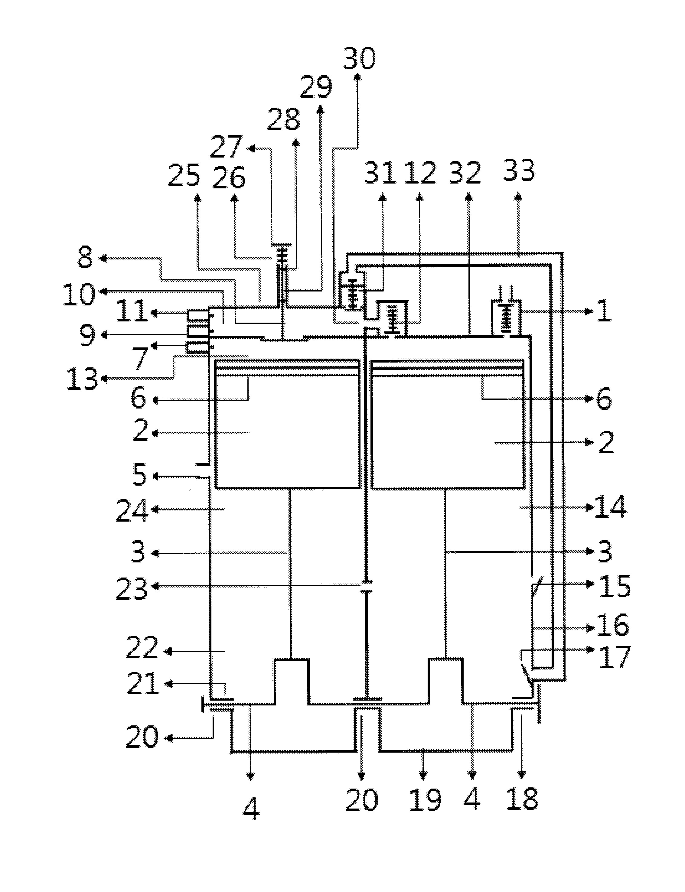
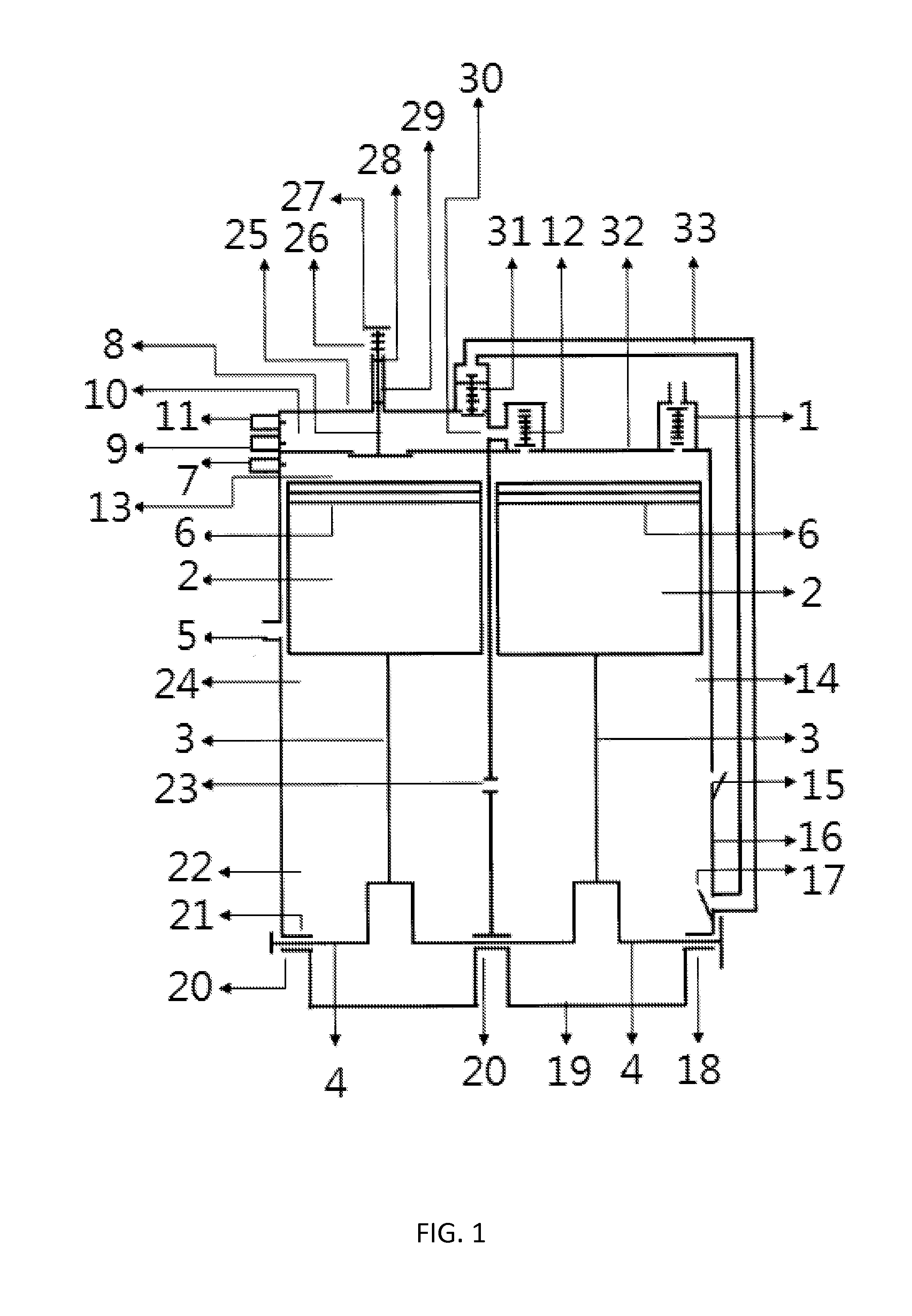
[0013]A. Main components: cylinder head (32) of compression cylinder (14) comprises mainly of intake valve (1) and exhaust valve (2), wherein intake valve (1) and exhaust valve (12) mainly comprises of valve and spring; pistons (2) for compression cylinder (14) and a expansion cylinder (24), mainly comprises of seal ring grooveseal ring (6)piston pinand piston pin seat, wherein the seal ring (6) is install in the seal ring groove, and the piston pin is install in the piston pin seat; connecting rod (3), mainly comprises of a small connecting rod header and a large connecting rod header; crankshaft (4), mainly comprises of a crankshaft main axle neckconnecting rod neckand crankshaft arm; cylinder head (25) of expansion cylinder (24), mainly comprises of a expansion chamber (13)combustion chamber (10)valve (8)valve sleeve (29)valve returning spring (26)and intake exhaust valve (31), wherein, the inside shape of the expansion chamber (13) and combustion chamber (10) is cylindrical and ...


PUM


Abstract

A two-stroke reciprocating piston engine. The engine principally consists of an expansion cylinder and a compression cylinder, and an expansion chamber and a combustion chamber. When pistons of the expansion cylinder and compression cylinder move from a bottom dead center to a top dead center, gas in the expansion cylinder is compressed in the expansion chamber, gas in the compression cylinder is compressed in the combustion chamber, a water spray nozzle sprays water towards the high temperature and high pressure gas in the expansion chamber, and when the water encounters the high temperature and high pressure gas, the water is rapidly vaporized. At the same time, an oil spray nozzle sprays a fuel into the combustion chamber, a spark from a spark plug ignites the combustible gas of the combustion chamber, the high temperature and high pressure gas produced by the combustion pushes open a valve of the combustion chamber.

Description

FIELD OF THE INVENTION[0001]Present invention relates to an internal combustion piston engine, especially a two-stroke reciprocating piston combustion engine.BACKGROUND OF THE INVENTION[0002]Known reciprocating internal combustion piston engines generally comprise the follow structural characteristics: 1. A crank connecting rods structure, which comprises a engine bodypistonsconnecting rod - and a crankshaft flywheel ; 2. Valve structure, which comprises intake and exhaust valves and camshafts; 3. Fuel supply structure, which comprises a fuel tankfuel pumpsand a carburetor(or a fuel nozzle); 4. Lubrication system, which comprises lubricating channeloil pumpfilterand oil valve; 5. Cooling system which comprises a water tankthermostatwater pumpcooling fanand water sleeve; 7. Ignition system, which comprises a batteryelectricity generatordistributorignition coiland spark plug; 7 starting system, which comprises a starter motor∘ In accordance with the number of strokes required to compl...

Claims


Application Information

Patent Timeline
Patent Type & Authority Applications(United States)
IPC IPC(8): F02M25/03
CPCF02M25/03F02B33/22F02M1/00F02M25/022Y02T10/12F02B3/06F02B47/02F02M2700/4321
Inventor LIU, GANG
Owner LIU GANG
Why Eureka
Try Eureka