
Method, apparatus and system for multi-antenna transmission

a multi-antenna transmission and apparatus technology, applied in diversity/multi-antenna systems, baseband system details, polarisation/directional diversity, etc., can solve problems such as degradation in precoding performance, and achieve the effect of improving system throughput and enhancing precoding performan

Active Publication Date: 2014-05-15
HUAWEI TECH CO LTD
View PDF2 Cites 4 Cited by
  • Summary
  • Abstract
  • Description
  • Claims
  • Application Information

AI Technical Summary

Benefits of technology

The invention provides a method, device, and system for multi-antenna transmission that improves precoding performance and increases system throughput. By using a third precoding matrix that matches the transmit spatial autocorrelation matrix of a cross-polarized antenna or distributed antenna, the first precoding matrix has a block diagonal structure and sub-matrices corresponding to two blocks are Hermitian matrices. This enables a more effective match and enhances precoding performance, resulting in improved system throughput.

Problems solved by technology

With regard to a distributed antenna configuration or a large-spacing cross-polarized antenna configuration, a precoding matrix obtained according to the above-mentioned design method can not match with a transmit spatial autocorrelation matrix, thereby resulting in a degradation in precoding performance.

Method used


Image

  • Method, apparatus and system for multi-antenna transmission
  • Method, apparatus and system for multi-antenna transmission
  • Method, apparatus and system for multi-antenna transmission

Examples


Embodiment Construction

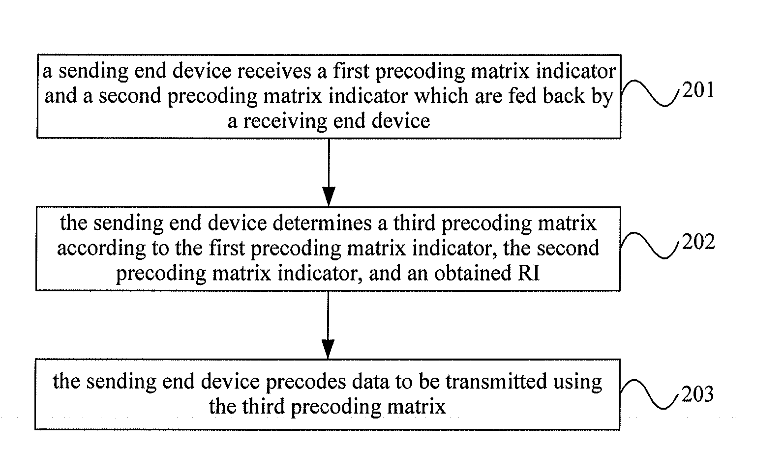
[0033]To make objectives, technical solutions and advantages of embodiments of the present invention clearer, a clear and complete description of technical solutions of the embodiments of the present invention will be given below, in combination with the accompanying drawings in the embodiments of the present invention. Apparently, the embodiments described below are a part, but not all, of the embodiments of the present invention. All of other embodiments, obtained by those skilled in the art based on the embodiments of the present invention without any inventive efforts, fall into the protection scope of the present invention.

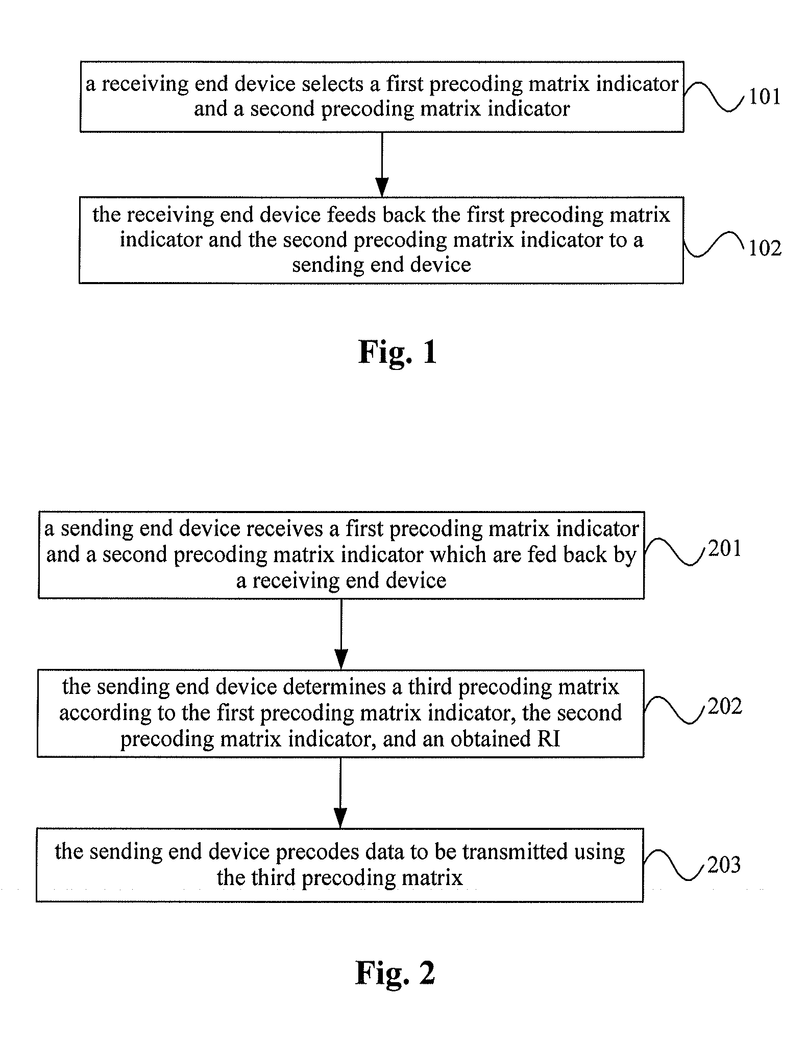
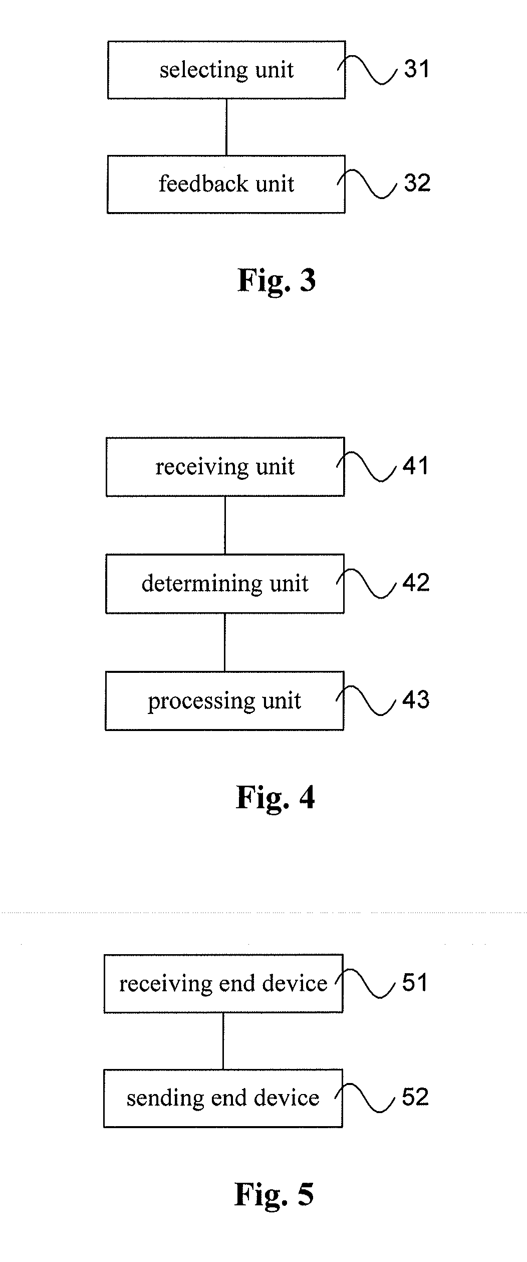
[0034]FIG. 1 is a schematic flowchart of a method for multi-antenna transmission provided by an embodiment of the present invention. As shown in FIG. 1, the method for multi-antenna transmission of the present embodiment may include:

[0035]101. a receiving end device selects a first precoding matrix indicator and a second precoding matrix indicator; and

[0036]1...


PUM


Abstract

Embodiments of the present invention provide a method, an apparatus and a system for multi-antenna transmission, wherein a third precoding matrix determined by a sending end device is a function of a first precoding matrix and a second precoding matrix. That the first precoding matrix has a block diagonal structure and that sub-matrices corresponding to two blocks are Hermitian matrices enable the above-mentioned third precoding matrix to match with a transmit spatial autocorrelation matrix of a cross-polarized antenna or a distributed antenna, thereby enhancing precoding performance and improving system throughput effectively.

Description

CROSS-REFERENCE TO RELATED APPLICATIONS[0001]The application is a continuation of International Application No. PCT / CN2012 / 078379, filed on Jul. 9, 2012, which claims priority to Chinese Patent Application No. 201110189461.4, filed on Jul. 7, 2011, both of which are hereby incorporated by reference in their entireties.FIELD OF INVENTION[0002]Embodiments of the present invention relate to communication technologies, and more particularly, to a method, an apparatus and a system for multi-antenna transmission.BACKGROUND OF THE INVENTION[0003]In multi-antenna transmission of a communication system, such as a long term evolution (Long Term Evolution, LTE for short) system and a long term evolution advanced (Long Term Evolution Advanced, LTE-A for short) system, a user equipment (User Equipment, UE for short) feeds back channel state information (Channel State Information, CSI for short) to a base station, such as an evolved node B (Evolved NodeB, eNB for short). The CSI includes a rank i...

Claims


Application Information

Patent Timeline
Patent Type & Authority Applications(United States)
IPC IPC(8): H04L25/03H04B7/04
CPCH04B7/0486H04L25/03923H04L1/06H04B7/0456H04B7/0617H04B7/0619H04B7/0665H04B7/0842H04B7/0469H04B7/0636H04B7/0639H04B7/10H04B7/0417
Inventor ZHOU, YONGXINGWANG, JIANGUO
Owner HUAWEI TECH CO LTD
Learn More