Redox flow battery

a technology of redox flow and battery, applied in the direction of indirect fuel cells, cell components, electrochemical generators, etc., can solve the problems of difficulty in maintaining frequency and voltage, power system operation, etc., and achieve stable charge and discharge characteristics, high electromotive force, and high electromotive force

Active Publication Date: 2014-05-15
SUMITOMO ELECTRIC IND LTD
View PDF3 Cites 27 Cited by
  • Summary
  • Abstract
  • Description
  • Claims
  • Application Information

AI Technical Summary

Benefits of technology

[0071]The redox flow battery according to the present invention has a high electromotive force. The redox flow battery according to the present invention can generate a high electromotive force and has stable charge and discharge characteristics.

Problems solved by technology

Since outputs of these power generations are affected by the weather, it is predicted that introduction on a large scale will cause problems with operation of power systems such as difficulty in maintaining frequencies and voltages.

Method used


Image

  • Redox flow battery
  • Redox flow battery
  • Redox flow battery

Examples


embodiments 1 to 12

[0095]Embodiments 1 to 12 are described below. RF batteries in Embodiments 1 to 12 have the above-described basic structure, and are characterized by including at least one of the above-described features (1) and (2).

embodiment 1

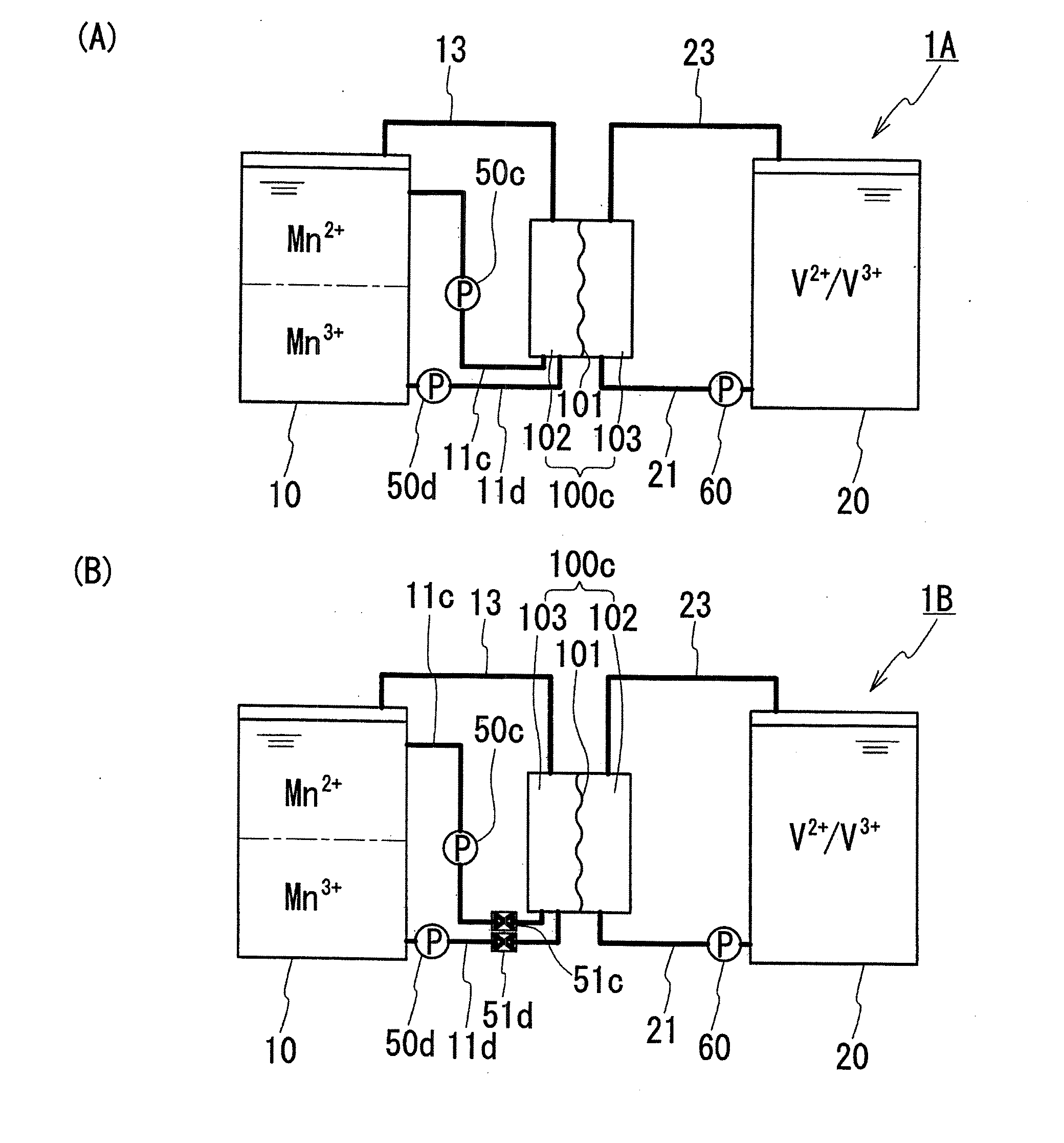
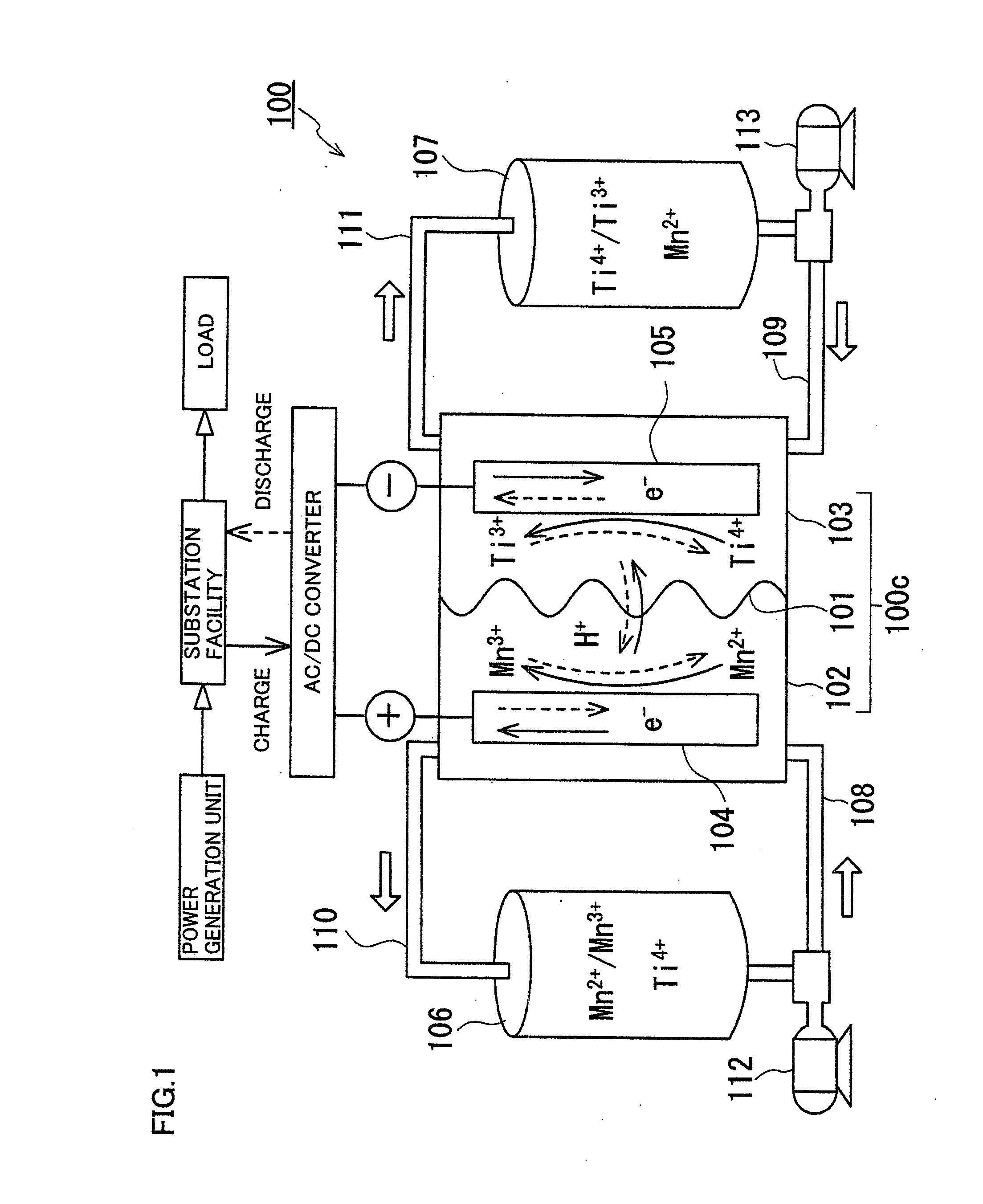
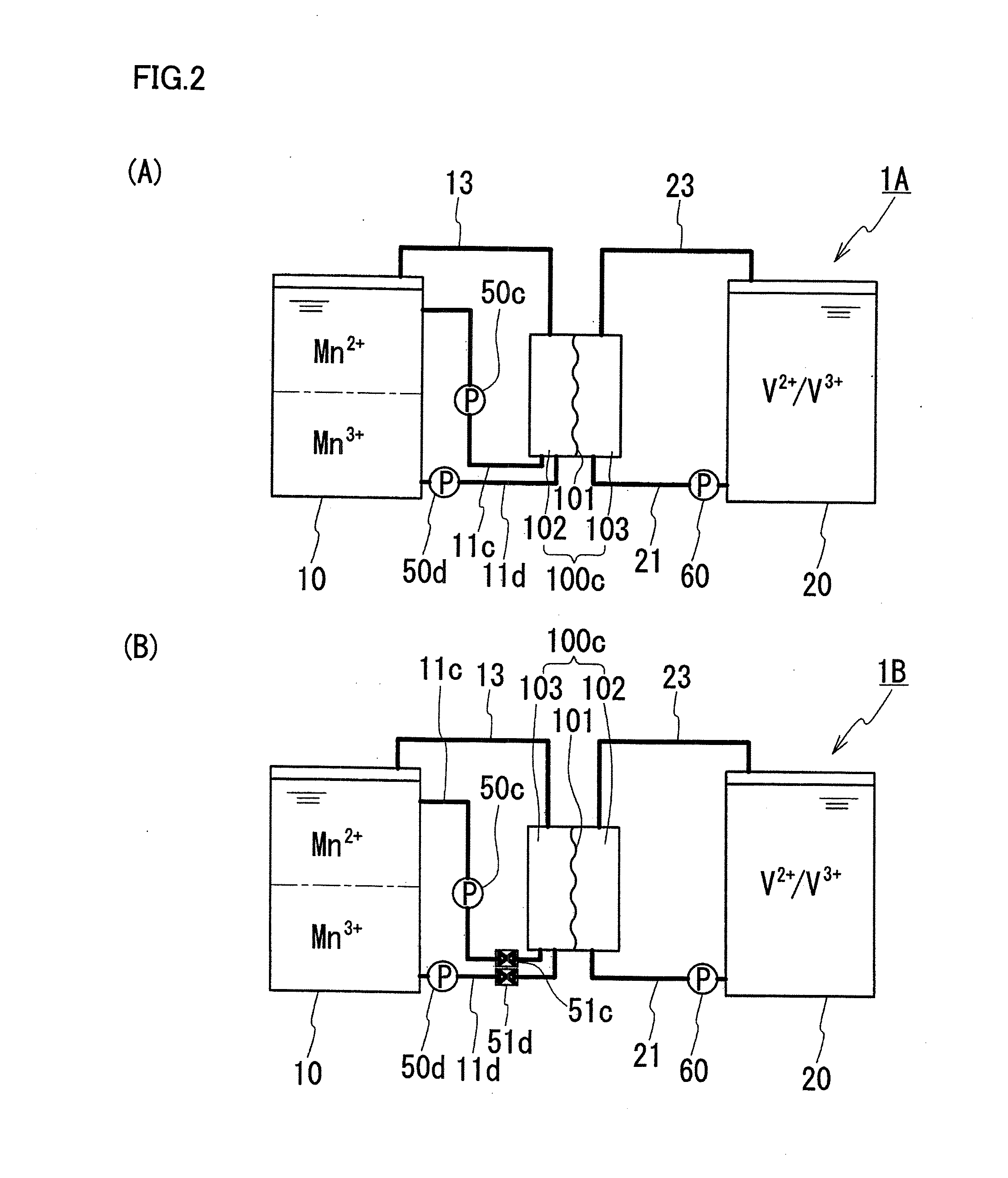
[0096]Referring to FIG. 2, an RF battery 1A in Embodiment 1 is described. RF battery 1A in Embodiment 1 has the above-described basic structure, and is characterized by using an electrolyte containing a Mn ion as a positive electrode active material as a positive electrode electrolyte, and by including two upstream pipes on the positive electrode side. These characteristic points will be mainly described below.

[0097][Electrolytes]

[0098]The positive electrode electrolyte contains at least one species of Mn ion selected from a divalent Mn ion (Mn2+) and a trivalent Mn ion (Mn3+). A study by the present inventors found that MnO2 can also be utilized as an active material. Accordingly, the present invention allows inclusion of tetravalent manganese (MnO2).

[0099]The negative electrode electrolyte contains, for example, as a negative electrode active material, at least one species of metal ion selected from a titanium ion, a vanadium ion, a chromium ion, a zinc ion, and a tin ion. A manga...

embodiment 2

[0112]An RF battery 1B in Embodiment 2 shown in FIG. 2(B) has a basic structure similar to that of RF battery 1A in Embodiment 1. RF battery 1B in Embodiment 2 is different in that it includes, in addition to the structure of RF battery 1A in Embodiment 1 shown in FIG. 2(A), on / off valves 51c and 51d provided on positive electrode charging pipe 11c and positive electrode discharging pipe 11d, respectively. This difference will be mainly described below, and the structure and effects common to RF battery 1A in Embodiment 1 will not be described in detail.

[0113]In RF battery 1B in Embodiment 2, a desired positive electrode electrolyte can be more reliably supplied to battery element 100c by operation of opening / closing on / off valves 51c and 51d, in addition to the control of supply of the positive electrode electrolyte by driving / stopping positive electrode pumps 50c and 50d. More specifically, during charge, the positive electrode electrolyte can be supplied from the liquid level sid...


PUM

PropertyMeasurementUnit
inner diameteraaaaaaaaaa
oxidation-reduction potentialsaaaaaaaaaa

Abstract

A redox flow battery charged and discharged by supply of a positive electrode electrolyte stored in a positive electrode tank and a negative electrode electrolyte stored in a negative electrode tank to a battery element, in which the positive electrode electrolyte contains a Mn ion as a positive electrode active material, and the positive electrode tank includes a positive electrode charging pipe opening to a position close to a liquid level of the positive electrode electrolyte in the positive electrode tank, and a positive electrode discharging pipe opening to a position close to the bottom of the positive electrode tank. This redox flow battery can include a stirring mechanism for stirring the electrolytes in the tanks, and can include a connection pipe connecting the positive electrode tank to the negative electrode tank.

Description

TECHNICAL FIELD[0001]The present invention relates to redox flow batteries. More particularly, the present invention relates to a redox flow battery capable of generating a high electromotive force.BACKGROUND ART[0002]As a way to combat global warming, introduction of new energy such as solar photovoltaic power generation and wind power generation has been promoted in recent years throughout the world. Since outputs of these power generations are affected by the weather, it is predicted that introduction on a large scale will cause problems with operation of power systems such as difficulty in maintaining frequencies and voltages. As a way to solve such problems, installation of large-capacity storage batteries for smoothing output variations, storing surplus power, and load leveling is expected.[0003]A redox flow battery is one of large-capacity storage batteries. A redox flow battery is charged and discharged by supply of a positive electrode electrolyte and a negative electrode e...

Claims


Application Information

Patent Timeline
Patent Type & Authority Applications(United States)
IPC IPC(8): H01M8/18H01M8/20
CPCH01M8/20H01M8/188H01M8/04119H01M8/04186Y02E60/50
Inventor KUMAMOTO, TAKAHIRODONG, YONGRONGSHIGEMATSU, TOSHIO
Owner SUMITOMO ELECTRIC IND LTD
Why Eureka
Try Eureka