Vehicle with air conditioner

a technology of air conditioner and vehicle, which is applied in the direction of machine operation, light and heating apparatus, transportation and packaging, etc., can solve the problems that future diesel and gasoline engines will not be able to provide the required waste heat, and achieve the effect of determining cabin comfort, good homogeneity, and positively affecting control quality

Inactive Publication Date: 2014-05-22
AUDI AG +1
View PDF6 Cites 5 Cited by
  • Summary
  • Abstract
  • Description
  • Claims
  • Application Information

AI Technical Summary

Benefits of technology

[0011]Additionally, the two heat exchanger rows are adjusted to one another so that a super cooling of the condensing refrigerant is performed in the first heat exchanger row in air flow direction. Functionally separated therefrom, at least a heat extraction and optionally also a condensation of the refrigerant provided by the compressor is performed in the second heat exchanger row. Heat extraction means cooling the refrigerant until it reaches the dew line of a Mollier diagram. Separating heat extraction / condensation and super cooling facilitates efficient and even air heating. Through the separation of heat exchanger surfaces for super cooling and heat extraction / condensation, a high condensation temperature is reached compared to cooling operations. Thus, the heat transfer from the supplemental heat exchanger to the inflowing air can also be provided with an increased driving temperature difference. The heater arrangement including the supplemental heat exchanger and the heater heat exchanger can easily cover the heating requirement also in extreme situations.
[0013]The two heat exchanger rows are flow-connected through a collector tube. The collector tube collects the liquid refrigerant exiting from the second heat exchanger row and transfers the liquid refrigerant to the first heat exchanger row. The collector tube can thus advantageously respectively open into a bottom side of the first and of the second heat exchanger row which easily facilitates collecting the condensing refrigerant in the collector tube. The collector tube can additionally include a separation cavity in which possibly refrigerant that is still in vapor state can be separated from the liquid refrigerant. This way a functional separation of the two heat exchanger rows between the heat extraction / condensation function and the super cooling function is obtained. The collector tube can be configured as a receiver. Furthermore, the collector can also be configured as a flat tube or as a double tube. Additionally, the collector tube can be positioned horizontally or vertically.

Problems solved by technology

Future diesel and gasoline engines will not be able to provide the required waste heat to heat a passenger compartment.

Method used


Image

  • Vehicle with air conditioner
  • Vehicle with air conditioner
  • Vehicle with air conditioner

Examples


Embodiment Construction

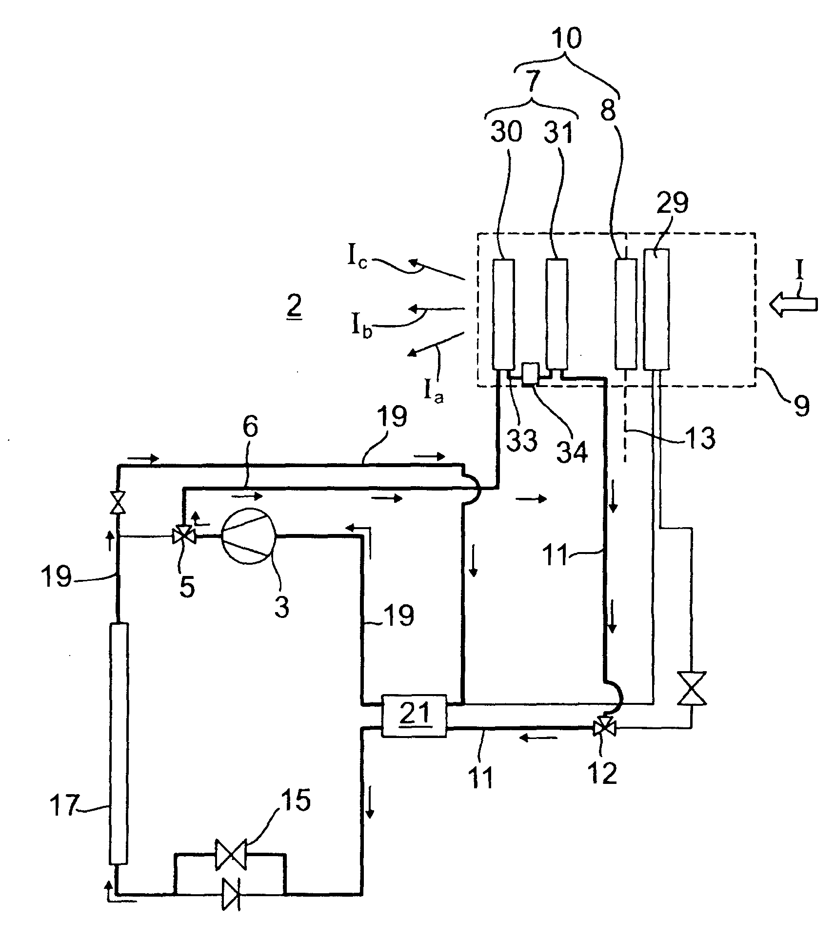
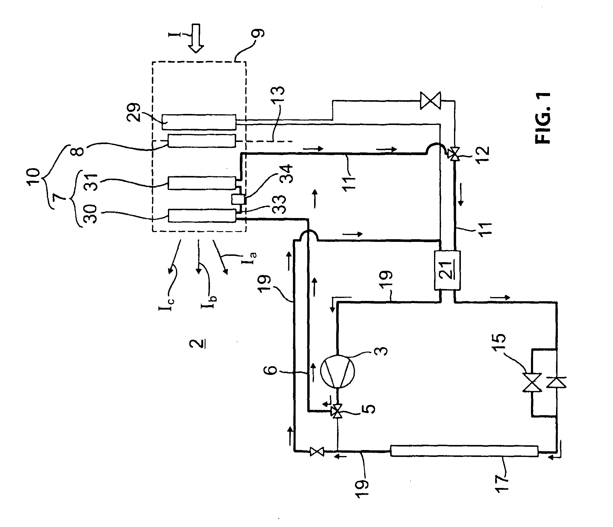
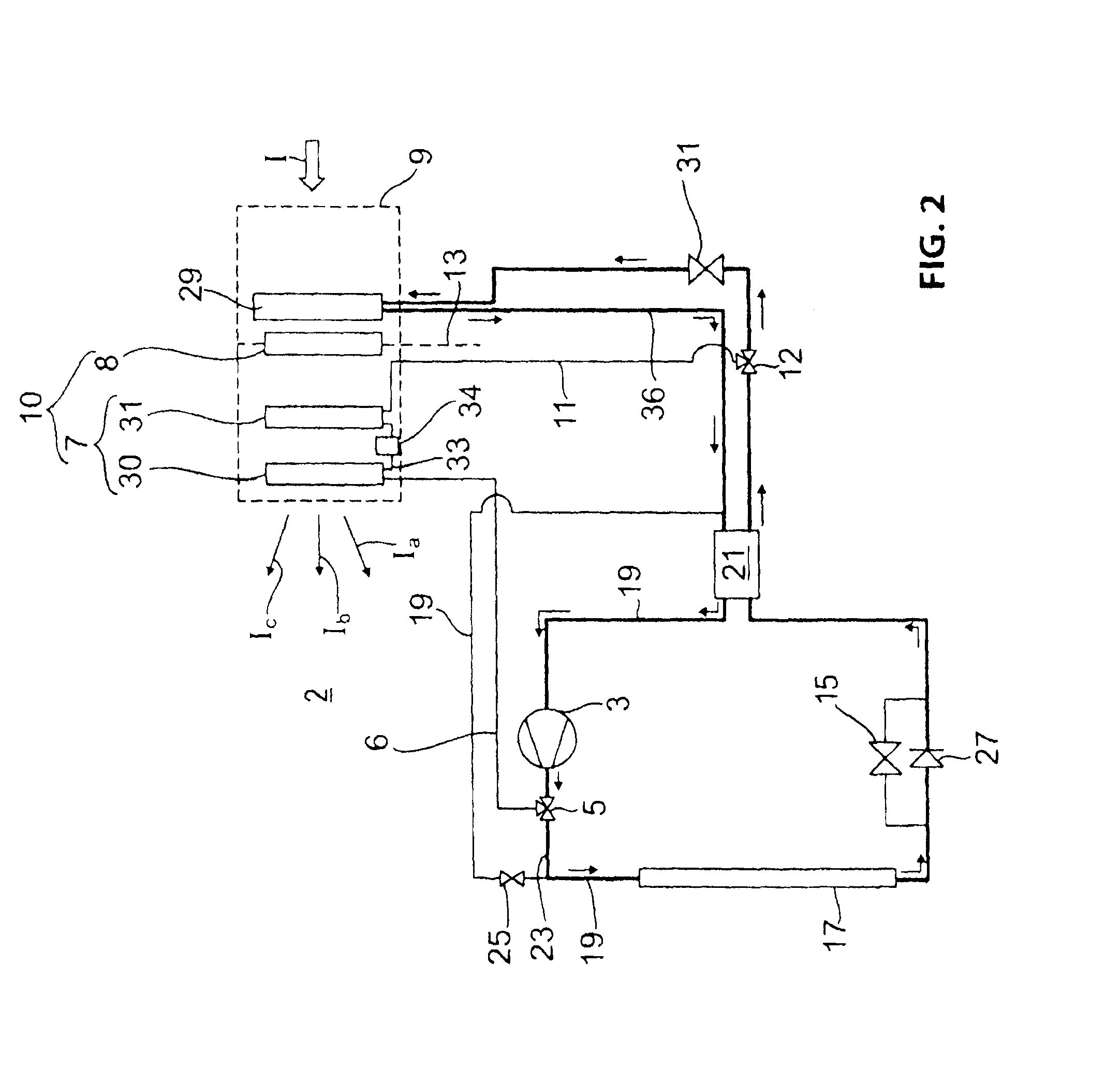
[0025]FIGS. 1 and 2 illustrate an air conditioner of a motor vehicle for cooling or heating a vehicle interior 2. FIG. 1 illustrates the heating mode for heating the vehicle interior 2, wherein the components flowed through with refrigerant are emphasized through thick lines over the components that are shut down in heating mode. Consequently, the refrigerant is run by a compressor 3 preferably through a 3 / 2 way valve into a first high pressure conduit 6 which leads to a supplemental heat exchanger 7 in arrow direction. The supplemental heat exchanger 7 is arranged in an air conditioning device drawn in dashed lines within an air channel of the air conditioning device 9, wherein incoming air I is run through the air channel into the vehicle interior 2. After heat up in the air conditioning device 9, hot air is run for example in three separate hot air streams Ia, Ib, Ic to various personal outlet valves, for example defrost valves, body valves and foot area valves.

[0026]The heat exc...


PUM


Abstract

The invention relates to a vehicle with an air conditioner for heating inlet air flowing into a vehicle interior, the air conditioner including: a heater heat exchanger thermally coupled through a coolant cycle with a drive unit or similar; and a supplemental heat exchanger which is connected to a refrigerant cycle of the air conditioner and which transfers heat to the inlet air in heating mode, wherein the supplemental heat exchanger is configured with at least two rows including a first heat exchanger row and a second heat exchanger row in a refrigerant flow direction, wherein the first heat exchanger row and the second heat exchanger row are arranged in a refrigerant flow direction so that super cooling of a condensed refrigerant is provided in the second heat exchanger row and at least heat extraction of the refrigerant is provided in the first heat exchanger row.

Description

RELATED APPLICATIONS[0001]This application is a continuation of PCT / EP2011 / 005484, filed on Oct. 29, 2011, claiming priority from German Patent Application DE 10 2010 051 471.3, filed on Nov. 15, 2010, both of which are incorporated in their entirety by this reference.FIELD OF THE INVENTION[0002]The invention relates to a vehicle with an air conditioner according to the preamble of patent claim 1.BACKGROUND OF THE INVENTION[0003]A vehicle interior is typically heated through a heater heat exchanger which is supplied with waste heat from a drive unit, for example an internal combustion engine, through a water based coolant cycle. Typically, a supplemental heater is associated with the heater heat exchanger. In vehicles with an air conditioner, the supplemental heater can be a condenser that is connected to the coolant cycle of the air conditioner, wherein the condenser transfers heat to air flowing into a vehicle interior during heating operations.[0004]From DE 102 53 357 B4, a vehic...

Claims


Application Information

Patent Timeline
Patent Type & Authority Applications(United States)
IPC IPC(8): B60H1/00
CPCB60H1/00921B60H2001/00957B60H1/00321
Inventor SCHROEDER, DIRKHAMMER, HANSREBINGER, CHRISTIANHEYL, PETER
Owner AUDI AG
Why Eureka
Try Eureka