

Semiconductor device and method of manufacturing the same
- Summary
- Abstract
- Description
- Claims
- Application Information
AI Technical Summary
Benefits of technology
Problems solved by technology
Method used
Image

Examples
Embodiment Construction
[0019]Hereinafter, various embodiments of the present invention will be described with reference to the accompanying drawings. In the drawings, a thicknesses and a distance of components are exaggerated compared to an actual physical thickness and interval for convenience of illustration. In the following description, detailed explanation of known related functions and constitutions may be omitted to avoid unnecessarily obscuring the subject manner of the present invention. Like reference numerals refer to like elements throughout the specification and drawings.
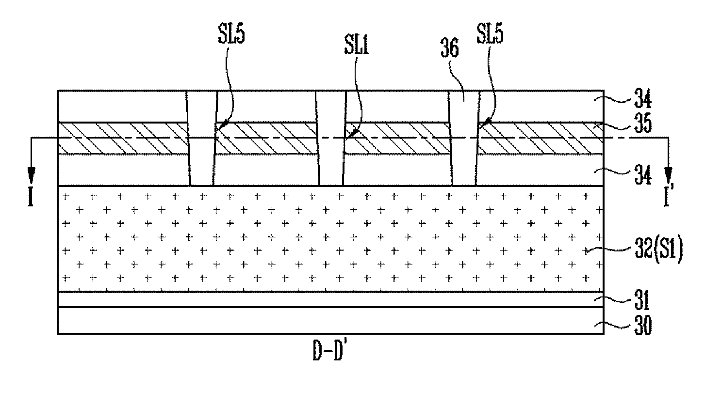
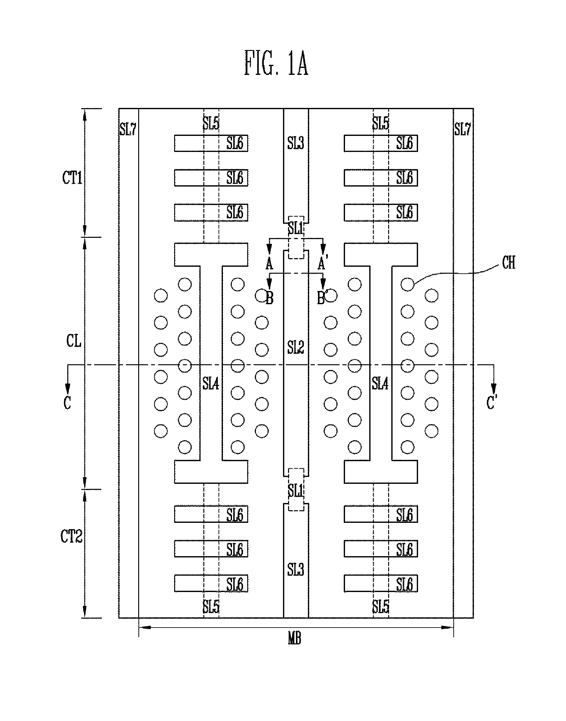
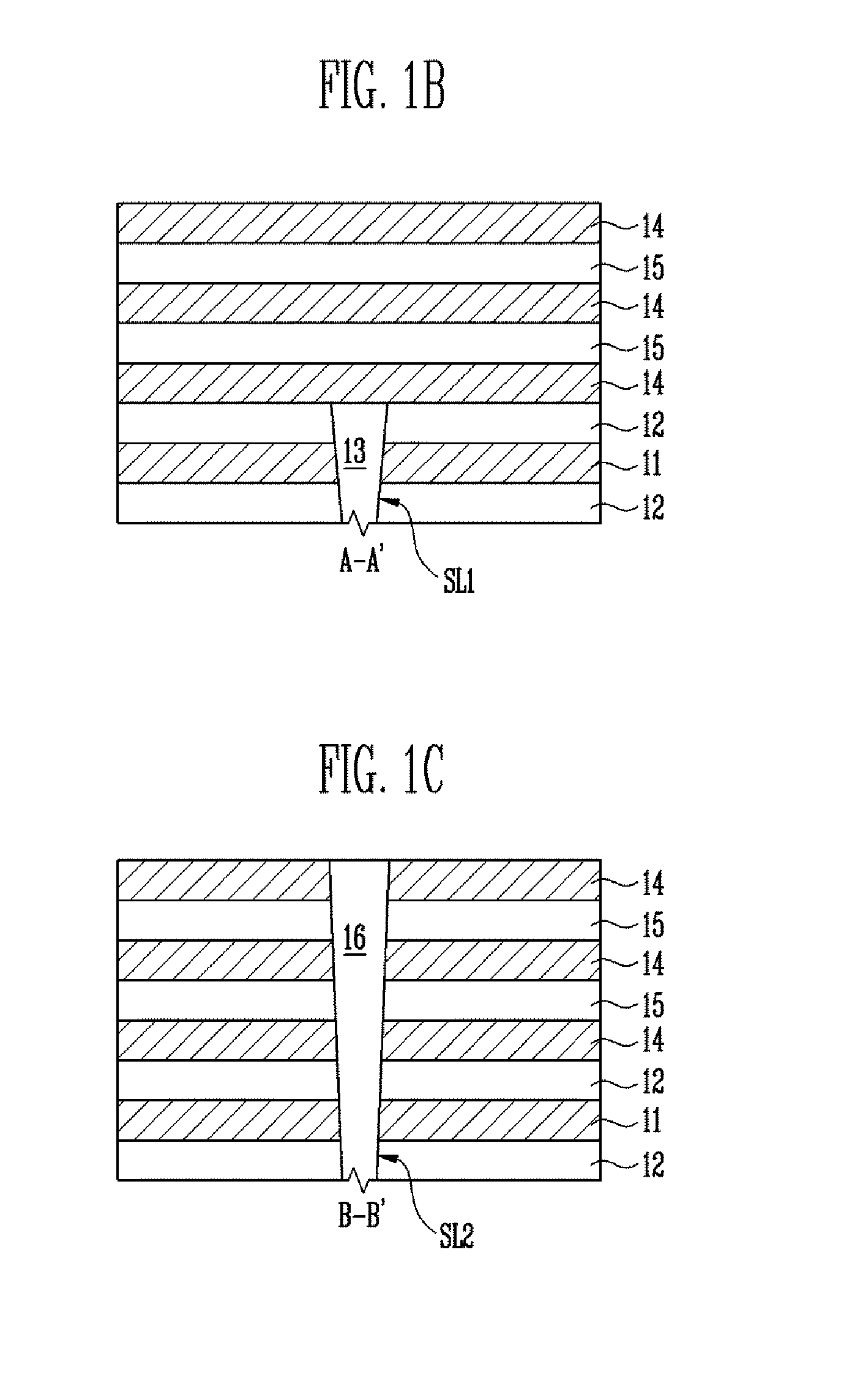
[0020]FIG. 1A is a layout view illustrating the structure of a semiconductor device according to an embodiment of the present invention. FIG. 1B is a cross-sectional view taken along line A-A′ of FIG. 1A. FIG. 1C is a cross-sectional view taken along line B-B′ of FIG. 1A.
[0021]As illustrated in FIGS. 1A to 1C, a semiconductor device according to an embodiment of the present invention may include a substrate (not illustrated),...
PUM
 Abstract
Description
Claims
Application Information