Object detection apparatus

a technology of object detection and object, which is applied in the field of object detection, can solve the problems that the replacement of the stereoscopic camera with the monocular camera cannot lead to proper detection of the object, and the accuracy of detecting the azimuth angle of the second object on the basis of the captured imag

Active Publication Date: 2014-05-22
DENSO CORP
View PDF10 Cites 53 Cited by
  • Summary
  • Abstract
  • Description
  • Claims
  • Application Information

AI Technical Summary

Benefits of technology

[0012]With this configuration, even when the first and second detection points do not coincide completely with each other, it may be determined that the first and second objects are the same. This can prevent a false determination that the first and second objects are different objects. Meanwhile, it is likely to be determined incorrectly that the first and second objects are the same although the first and second objects are actually different objects.
[0013]In the apparatus of the present embodiment, the second object domain is defined by a second azimuthal range of azimuth angle of the second object from the forward direction of the vehicle. This can prevent false determinations. That is, accuracy of detecting the azimuth angle of the second object on the basis of the captured image from the monocular camera is relatively high. Defining the second object domain by using such a second azimuthal range of azimuth angle leads to the second object domain being suited for characteristics of the monocular camera, as compared to cases where the second object domain is defined by an X-coordinate range that is constant in width over X-coordinates. This can prevent false determinations.

Problems solved by technology

However, the monocular camera and the stereoscopic camera are quite different from each other in principle of detecting a position, particularly, a forward distance, of an object relative to the controlled vehicle, and accuracy of detecting the forward distance of the object by the monocular camera is much lower than accuracy of detecting the forward distance of the object by the stereoscopic camera.
Therefore, replacement of the stereoscopic camera with the monocular camera cannot lead to proper detection of the object.

Method used


Image

  • Object detection apparatus
  • Object detection apparatus
  • Object detection apparatus

Examples


first embodiment

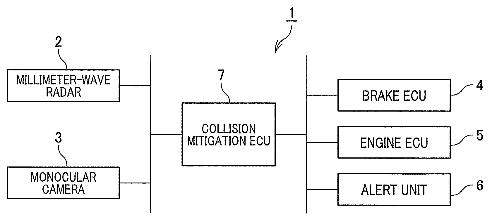
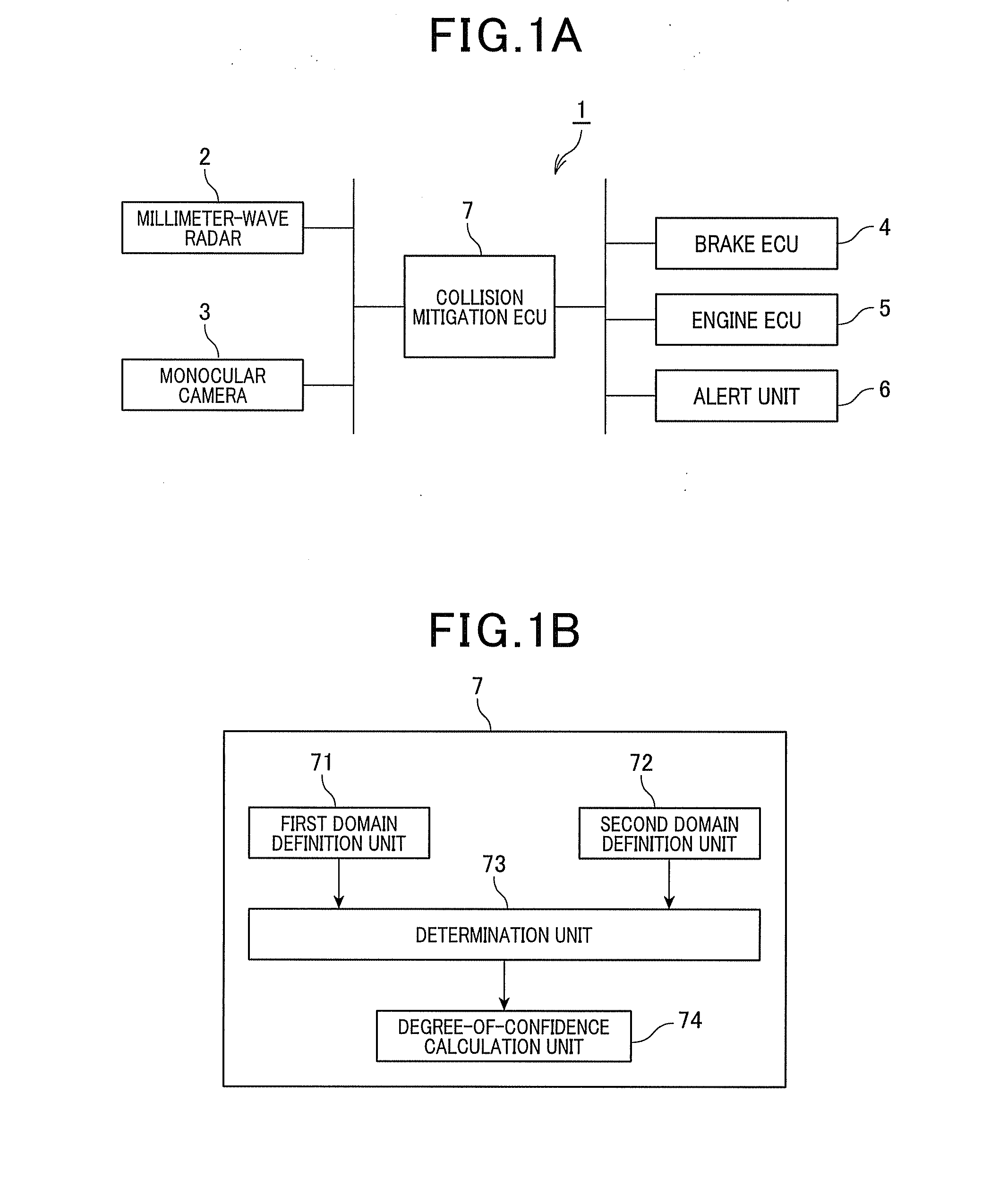
[0034]FIG. 1A shows a schematic diagram of a collision mitigation apparatus 1 in accordance of a first embodiment of the present invention. The collision mitigation apparatus 1 is mounted in a vehicle (hereinafter referred to as a subject vehicle), and includes a millimeter-wave radar 2, a monocular camera 3, a brake electronic control unit (ECU) 4, an engine ECU 5, an alert unit 6, and a collision mitigation ECU 7. In the collision mitigation apparatus 1, for example, the collision mitigation ECU 7 is communicably connected to the millimeter-wave radar 2, the monocular camera 3, the brake ECU 4, the engine ECU 5, and the alert unit 6.

[0035]The millimeter-wave radar 2 is mounted in the front middle portion of the subject vehicle to detect objects, such as other vehicles and pedestrians, by using millimeter waves. The millimeter-wave radar 2 transmits millimeter waves forward from the subject vehicle while scanning in a horizontal plane and receives millimeter waves reflected back to...

second embodiment

[0073]There will now be explained a second embodiment of the present invention. Only differences of the second embodiment from the first embodiment will be explained.

[0074]In the first embodiment described above, the radar error domain Rr is defined by an X-coordinate range of assumed error in the X-coordinate, centered at the X-coordinate of the detection point Pr, and a Y-coordinate range of assumed error in the Y-coordinate, centered at the Y-coordinate of the detection point Pr, where the assumed errors in the X- and Y-coordinates are predetermined on the basis of the characteristics of the millimeter-wave radar 2.

[0075]Alternatively, in the present embodiment, a radar error domain Rr is defined by a horizontal azimuth angle range of assumed error in the horizontal azimuth angle, centered at the horizontal azimuth angle of the detection point Pr, and a Y-coordinate range of assumed error in the Y-coordinate, centered at the Y-coordinate of the detection point Pr, where the assum...

third embodiment

[0078]There will now be explained a third embodiment of the present invention. Only differences of the third embodiment from the second embodiment will be explained.

[0079]In the second embodiment, as described above, the radar error domain Rr and the image error domain Ri are defined in a similar manner to each other. As shown in FIG. 6, the radar error domain Rr is defined by a horizontal azimuth angle range of assumed error in the horizontal azimuth angle, centered at the horizontal azimuth angle of the detection point Pr, and a Y-coordinate range of assumed error in the Y-coordinate, centered at the Y-coordinate of the detection point Pr. Similarly, the image error domain Ri is defined by a horizontal azimuth angle range of assumed error in the horizontal azimuth angle, centered at the horizontal azimuth angle of the detection point Pi, and a Y-coordinate range of assumed error in the Y-coordinate, centered at the Y-coordinate of the detection point Pi.

[0080]Alternatively, in the...


PUM


Abstract

An object detection apparatus mounted in a vehicle, includes a first domain definition unit, a second domain definition unit, and a determination unit. The first domain definition unit defines a first object domain including a first detection point which is indicative of a position of a first object detected by using a vehicle-mounted radar. The second domain definition unit defines a second object domain including a second detection point which is indicative of a position of a second object detected on the basis of an image captured by a vehicle-mounted monocular camera. The determination unit determines whether or not an overlapping domain of the first and second object domains is present, and when it is determined that an overlapping domain of the first and second object domains is present, then determines that the first and second objects are the same.

Description

CROSS-REFERENCE TO RELATED APPLICATION[0001]This application is based on and claims the benefit of priority from earlier Japanese Patent Applications No. 2012-256331 filed Nov. 22, 2012 and No. 2013-177014 filed Aug. 28, 2013, the descriptions of which are incorporated herein by reference.BACKGROUND[0002]1. Technical Field[0003]The present invention relates to detection of an object by using a radar and a camera.[0004]2. Related Art[0005]A vehicle collision avoidance system is required to accurately detect an object, such as a vehicle other than, a controlled vehicle (i.e., a vehicle in which the system is mounted) or a pedestrian. A vehicle collision avoidance system, as disclosed in Japanese Patent Application Laid-Open. Publication No. 2006-292475, is configured to detect an object by using a radar and a camera. More specifically, the disclosed vehicle collision avoidance system uses a millimeter-wave radar and a stereoscopic camera separately, and determines that an object detec...

Claims


Application Information

Patent Timeline
Patent Type & Authority Applications(United States)
IPC IPC(8): G01S13/86G01S13/931
CPCG01S13/50G01S13/867G01S13/931B60R21/013B60W30/08G01S13/86G01V8/10
Inventor BABA, TAKAHIRO
Owner DENSO CORP
Why Eureka
Try Eureka