Radiation generating apparatus and radiation imaging apparatus

a radiation generation apparatus and radiation imaging technology, applied in the direction of x-ray tubes, x-ray tube details, x-ray tube vessels, etc., can solve the problems of 99% of power consumption becoming heat, the radiation generation efficiency is significantly low, etc., to achieve the effect of effectively radiating the heat of a target, reducing the weight of the radiation generating apparatus, and ensuring the performance of shielding unnecessary radiation

Inactive Publication Date: 2014-05-22
CANON KK
View PDF5 Cites 21 Cited by
  • Summary
  • Abstract
  • Description
  • Claims
  • Application Information

AI Technical Summary

Benefits of technology

[0010]The present invention can secure performance of shielding unnecessary radiation, and effectively radiate the heat of a target. Furthermore, the thermal conducting member having a lower density than the radiation shielding member is adopted. Accordingly, the entire weight of the radiation generating apparatus can be reduced. This configuration allows radiation imaging with a large tube current and a microfocus, and enables a high resolution taken image to be acquired. Moreover, reduction in size and weight facilitates application to home medical testing and emergency on-site medical testing.
[0011]Further features of the present invention will become apparent from the following description of exemplary embodiments with reference to the attached drawings.

Problems solved by technology

However, in general, the radiation generation efficiency is significantly low, and about 99% of power consumption becomes heat.

Method used


Image

  • Radiation generating apparatus and radiation imaging apparatus
  • Radiation generating apparatus and radiation imaging apparatus
  • Radiation generating apparatus and radiation imaging apparatus

Examples


example 1

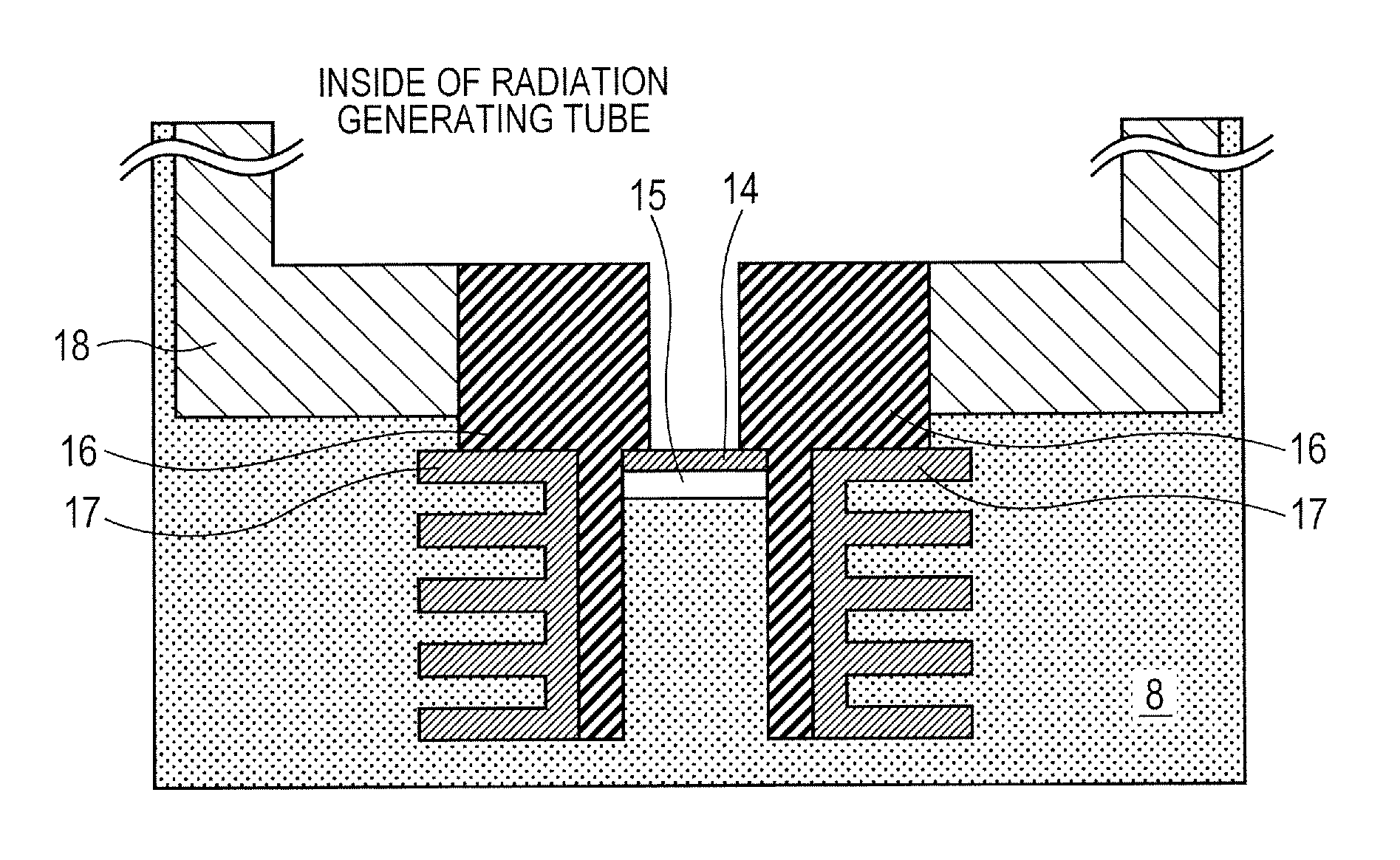
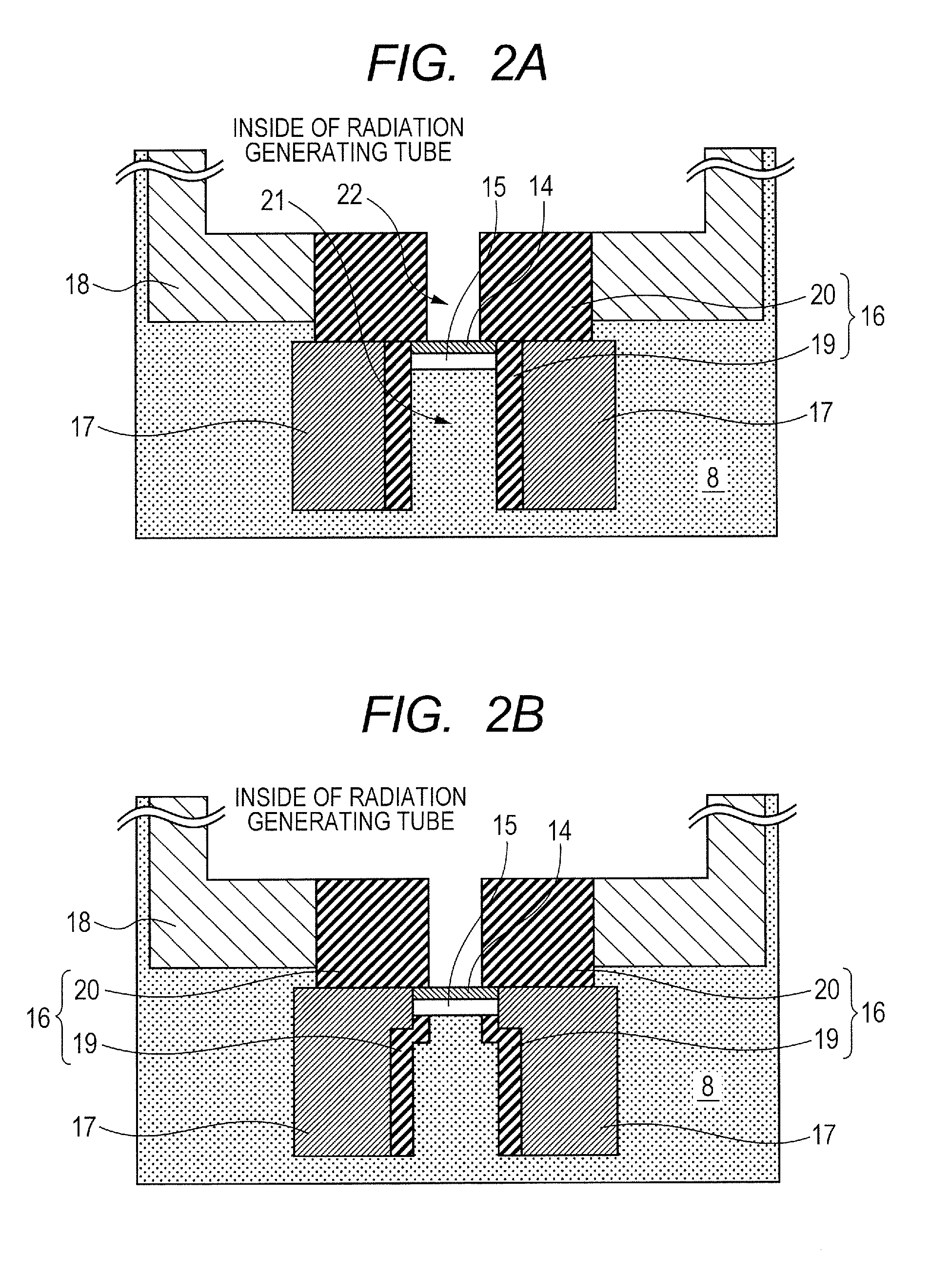
[0042]Tungsten is selected for the shielding member 16, into which the first shielding member 19 and the second shielding member 20 are formed in the integrated manner as illustrated in FIG. 2A. Copper is selected for the thermal conducting member 17. The thermal conducting member 17 is fixed by brazing to the outer periphery of a portion protruding from the second window 15 of the shielding member 16 toward the first window 2. An insulating oil made of a mineral oil is adopted as the insulating fluid 8. Midpoint grounding is used for voltage control. A tungsten filament is adopted as the electron emitting source 5, which is heated by a heating unit, not illustrated, to emit electrons. The emitted electrons are accelerated to a high energy, according to electron beam trajectory control by a potential distribution caused by a voltage applied to the extraction electrode and the lens electrode, and the voltage Va applied between the electron emitting source 5 and the target 14, thereby...

example 2

[0043]As illustrated in FIG. 2B, in this example, the first shielding member 19 and the second shielding member 20 are disposed separately. The thermal conducting member 17 is disposed at an outer periphery of the first shielding member 19 such that a part of the thermal conducting member 17 is in directly contact with the second window 15. This example is similar in configuration to Example 1 except that a part of heat generated at the second window 15 is directly conducted to the thermal conducting member 17 without intervention of the first shielding member 19 and thereby the heat radiation speed is further increased.

example 3

[0044]As illustrated in FIG. 2C, in this example, the thermal conducting member 17 is connected to a part of an outer periphery of a protrusion of the shielding member 16 and also provided between the wall surface of the aperture portion of the evacuated container 9 and the shielding member 16. This example is similar in configuration to Example 1 except for this point.


PUM


Abstract

A radiation generating apparatus of the present invention includes an envelope 1 including a first window 2 allowing radiation to pass; a radiation tube 10 that is accommodated in the envelope 1, and includes a second window 15 allowing radiation to pass, at a position opposite to the first window 2; a radiation passing hole 21 that is thermally connected to the second window 15 and communicates with the second window 15; and a radiation shielding member 16 protruding from the second window 15 toward the first window 2. In this apparatus, a thermal conducting member 17 having a higher thermal conductivity than the radiation shielding member 16 is connected to an outer periphery of the protruding portion of the radiation shielding member 16. The simple configuration can shield unnecessary radiation, and cool the target, while facilitating reduction in weight.

Description

TECHNICAL FIELD[0001]The present invention relates to a radiation generating apparatus and a radiation imaging apparatus using the same that are applicable to medical apparatuses and non-destructive X-ray imaging in industrial apparatus fields.BACKGROUND ART[0002]In general, a radiation tube accelerates electrons emitted from an electron emitting source by a high voltage, and irradiates a target to thereby generate radiation, such as X-rays. The radiation generated at this time is emitted in all directions. PTL 1 discloses a transmission X-ray generating apparatus including an X-ray shielding member disposed on an electron incident side and an X-ray emitting side with respect to a target for shielding unnecessary X-rays.[0003]It is required to apply a high voltage between the electron emitting source and the target to irradiate the target with a high energy electron beam, to generate radiation suitable for radiation imaging. However, in general, the radiation generation efficiency i...

Claims


Application Information

Patent Timeline
Patent Type & Authority Applications(United States)
IPC IPC(8): H01J35/12H01J35/16
CPCH01J35/16H01J35/12H01J2235/122H01J2235/166H05G1/025H05G1/04H01J35/13H01J35/186G01N23/04
Inventor YANAGISAWA, YOSHIHIROUEDA, KAZUYUKINOMURA, ICHIROTAMURA, MIKIAOKI, SHUJISANDO, KAZUHIRO
Owner CANON KK
Why Eureka
Try Eureka