Carbon dioxide separation system

a separation system and carbon dioxide technology, applied in the direction of separation processes, gaseous fuels, fuels, etc., can solve the problems of high energy consumption for the regeneration of absorbing liquids or adsorbents, and achieve high selectivity, high durability, and high selectivity

Active Publication Date: 2014-05-29
HITACHI ZOSEN CORP
View PDF9 Cites 14 Cited by
  • Summary
  • Abstract
  • Description
  • Claims
  • Application Information

AI Technical Summary

Benefits of technology

[0024]The invention of claim 1, the carbon dioxide separation system, is characterized in that a mixed gas (1) having a carbon dioxide concentration of 3 to 75% is introduced into a primary carbon dioxide separation device (4) equipped with a zeolite membrane (5) for carbon dioxide separation to produce a primary permeated gas (6) having a carbon dioxide concentration of 80% or more on the permeate side of the zeolite membrane (5) for carbon dioxide separation and also reduce the carbon dioxide concentration of a primary gas (7) on the non-permeate side of the zeolite membrane (5) for carbon dioxide separation to 3 to 15%, and then the primary gas (7) on the non-permeate side is introduced into a secondary carbon dioxide separation device (8) that employs an amine absorption method or a pressure swing adsorption method (PSA) to produce a secondary separated gas (9) having a carbon dioxide concentration of 80% or more separated, by the secondary carbon dioxide separation device (8) and also produce a carbon-dioxide-removed gas (10) having a carbon dioxide concentration of 2% or less. The invention of claim 1 is advantageous in that a mixed gas having a wide range of carbon dioxide concentration and pressure can be efficiently separated into a high-concentration carbon dioxide gas and a carbon-dioxide-removed gas.
[0025]The invention of claim 2, the carbon dioxide separation system, is characterized in that a mixed gas (1) having a carbon dioxide concentration of 3 to 75% is introduced into a primary carbon dioxide separation device (4) equipped with a zeolite membrane (5) for carbon dioxide separation to produce a primary permeated gas (6) containing permeated carbon dioxide on the permeate side of the zeolite membrane (5) for carbon dioxide separation and also reduce the carbon dioxide concentration of a primary gas (7) on the non-permeate side of the zeolite membrane (5) for carbon dioxide separation to 3 to 15%, then the primary gas (7) on the non-permeate side is introduced into a secondary carbon dioxide separation device (8) that employs an amine absorption method or a pressure swing adsorption method (PSA) to produce a secondary separated gas (9) containing carbon dioxide separated by the secondary carbon dioxide separation device (8) and also produce a carbon-dioxide-removed gas (10) having a carbon dioxide concentration of 2% or less, and the primary permeated gas (6) containing carbon dioxide discharged from the zeolite membrane (5) for carbon dioxide separation and the secondary separated gas (9) containing carbon dioxide discharged from the secondary carbon dioxide separation device (8) are mixed to produce a carbon-dioxide-concentrated gas (11) having a carbon dioxide concentration of 80% or more. Th

Problems solved by technology

However, because the energy consumption for the regeneration of the absorbing liquid or ad

Method used


Image

  • Carbon dioxide separation system
  • Carbon dioxide separation system
  • Carbon dioxide separation system

Examples


example 1

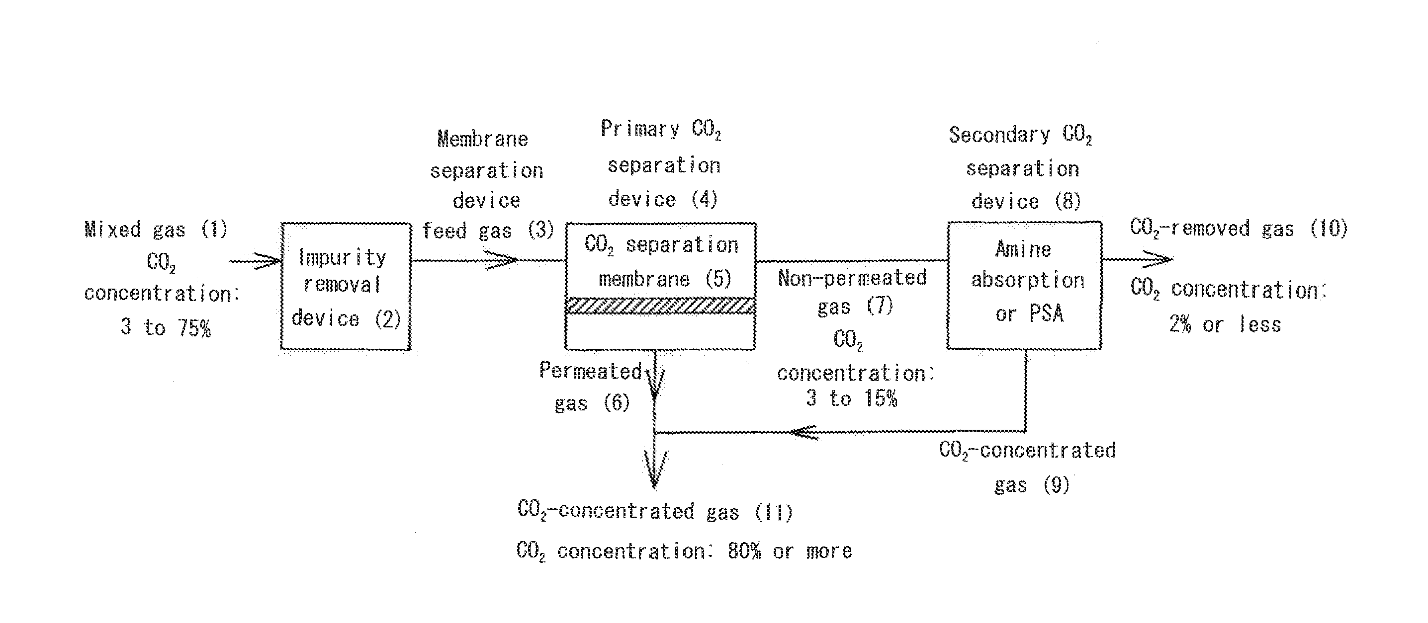
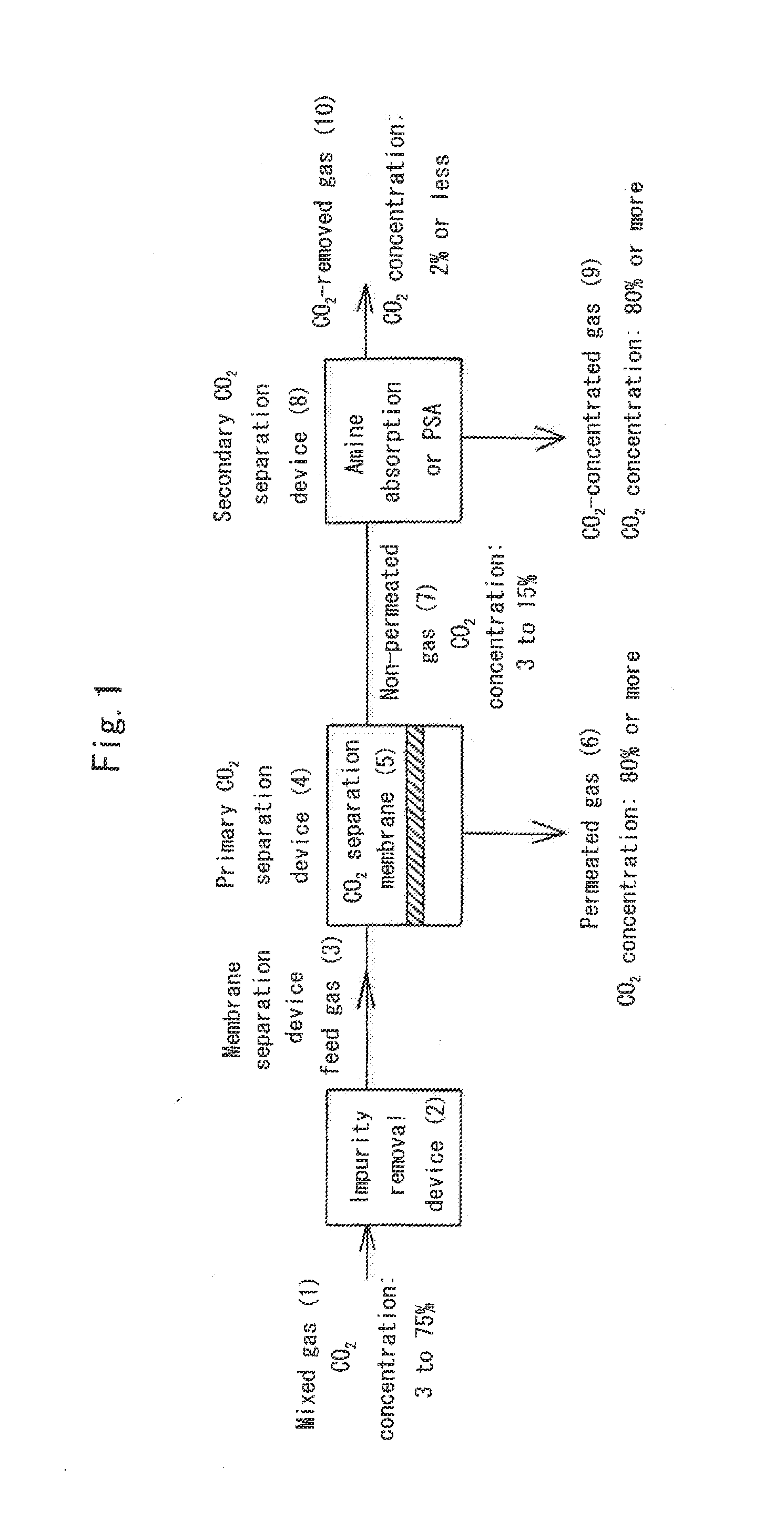
[0074]The carbon dioxide separation and recovery system of the invention was implemented according to the flow sheet shown in FIG. 1.

[0075]With reference to the figure, a mixed gas (1) having a carbon dioxide concentration of 20% containing carbon dioxide (CO2) and also containing nitrogen (N2), oxygen (O2), and impurities including water (H2O), hydrogen sulfide (H2S) nitrogen oxides (NOx), and sulfur oxides (SOx) was first introduced into an upstream impurity removal device (2) equipped with an adsorbent, such as zeolite, for removing the impurities. As a result, a primary carbon dioxide separation device (4) and a zeolite membrane (5) for carbon dioxide separation, which are provided downstream, were successfully prevented from being contaminated and degraded by the impurities.

[0076]Next, a membrane separation device feed gas (3) was introduced into the primary carbon dioxide separation device (4) equipped with the zeolite membrane (5) for carbon dioxide separation. Here, as the z...

example 2

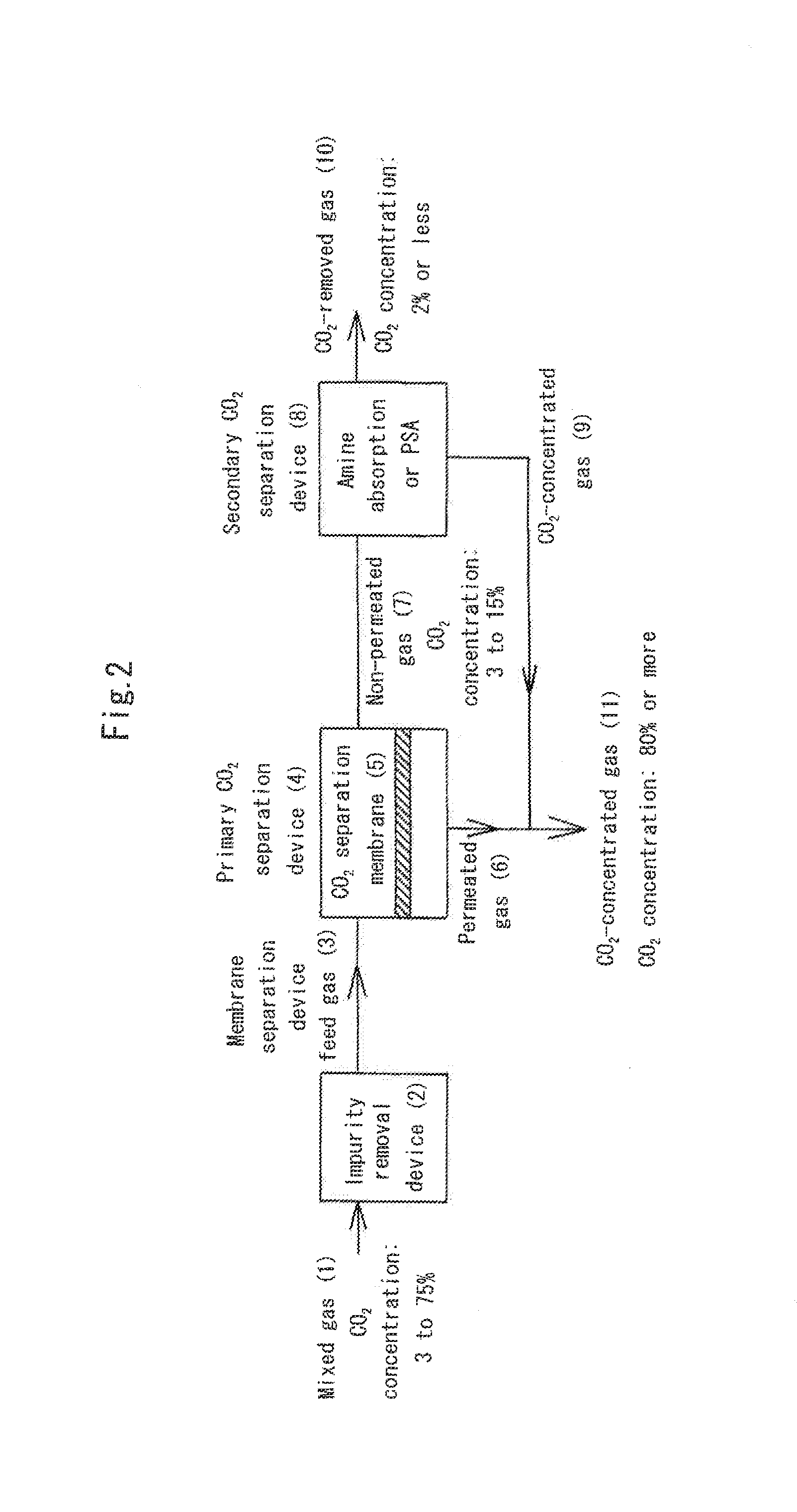
[0083]The carbon dioxide separation and recovery system of the invention was implemented according to the flow sheet shown in FIG. 2. Here, the difference from Example 1 is that a primary gas (7) on the non-permeate side of a zeolite membrane (5) for carbon dioxide separation was introduced into a secondary carbon dioxide separation device (8) that employs a pressure swing adsorption (PSA) method using zeolite 13X as a carbon dioxide recovery / separation material to produce a secondary separated gas (9) containing carbon dioxide separated by the secondary carbon dioxide separation device (8) and also produce a carbon-dioxide-removed gas (10) having a carbon dioxide concentration of 2% or less, and a primary permeated gas (6) containing carbon dioxide discharged from the zeolite membrane (5) for carbon dioxide separation and the secondary separated gas (9) containing carbon dioxide discharged from the secondary carbon dioxide separation device (8) were mixed to produce a carbon-dioxid...


PUM


Abstract

In the carbon dioxide separation system, a mixed gas having a carbon dioxide concentration of 3 to 75% is introduced into a primary carbon dioxide separation device equipped with a zeolite membrane for carbon dioxide separation to produce a primary permeated gas having a carbon dioxide concentration of 80% or more on the permeate side of the zeolite membrane and also reduce the carbon dioxide concentration of a primary gas on the non-permeate side of the zeolite membrane to 3 to 15%. Next, the primary gas on the non-permeate side is introduced into a secondary carbon dioxide separation device that employs an amine absorption method or a pressure swing adsorption (PSA) method to produce a secondary separated gas having a carbon dioxide concentration of 80% or more separated by the separation device and also produce a carbon-dioxide-removed gas having a carbon dioxide concentration of 2% or less.

Description

TECHNICAL FIELD[0001]The present invention relates to a carbon dioxide separation system for recovering carbon dioxide (CO2) from a mixed gas having a carbon dioxide concentration of 3 to 75%.BACKGROUND ART[0002]In recent years, carbon dioxide, a typical global warming gas, has been discharged from power plants, cement plants, steel plants, chemical plants, etc. In terms of the prevention of global warming, there an urgent need to develop a high-efficiency carbon dioxide recovery technology. In addition, carbon dioxide is also present in natural gases containing methane as a main component, and, in terms of the prevention of pipeline corrosion, carbon dioxide needs to be recovered and removed from methane in addition, in an integrated coal gasification combined cycle, an attempt has been made in which finely pulverized coal is pyrolyzed and gasified to produce, through a shift reaction, a gas containing hydrogen and carbon dioxide as main components, and then carbon dioxide is separ...

Claims


Application Information

Patent Timeline
IPC IPC(8): B01D71/02B01D53/047B01D53/14B01D53/22C01B32/50
CPCB01D53/047B01D53/1475B01D53/22B01D53/229B01D71/028B01D2257/504C10L3/101C10L3/104Y02C20/40B01D53/1493
Inventor SAWAMURA, KEN-ICHITAKAKI, YOSHINOBUASARI, YOSHIHIRO
Owner HITACHI ZOSEN CORP
Why Eureka
Try Eureka