
Apparatus and method for measuring position deviation of rotor of permanent magnet synchronous motor

a technology of synchronous motor and apparatus, which is applied in the direction of motor/generator/converter stopper, dynamo-electric converter control, dynamo-electric gear control, etc., can solve the problems of reducing the flexibility of use, requiring a large amount of calculation, and not being generally applicabl

Active Publication Date: 2014-05-29
DELTA ELECTRONICS INC
View PDF37 Cites 17 Cited by
  • Summary
  • Abstract
  • Description
  • Claims
  • Application Information

AI Technical Summary

Benefits of technology

The present invention provides an apparatus and method for measuring position deviation of a motor rotor without using an external device, such as a mechanical contracting brake apparatus. This method is convenient, efficient, and flexible, reducing the time and cost for the entire measuring process. It allows for position (or angle) compensation values to be measured in various application situations, making it more practical for use.

Problems solved by technology

However, the aforementioned method requires a large amount of calculation and depends on the accuracy of the parameters of the motor main body, and the parameters of the motor main body always cannot be obtained precisely, so that the aforementioned method is not generally applicable.
As a result, problems such as inconvenience for utilization and poor efficiency are caused in actual operation, also resulting in the condition of limiting the measuring method and limiting the utilization thereof in certain situations, thereby reducing the flexibility of usage and directly increasing the difficulty in application of the aforementioned measuring method.

Method used


Image

  • Apparatus and method for measuring position deviation of rotor of permanent magnet synchronous motor
  • Apparatus and method for measuring position deviation of rotor of permanent magnet synchronous motor
  • Apparatus and method for measuring position deviation of rotor of permanent magnet synchronous motor

Examples


Embodiment Construction

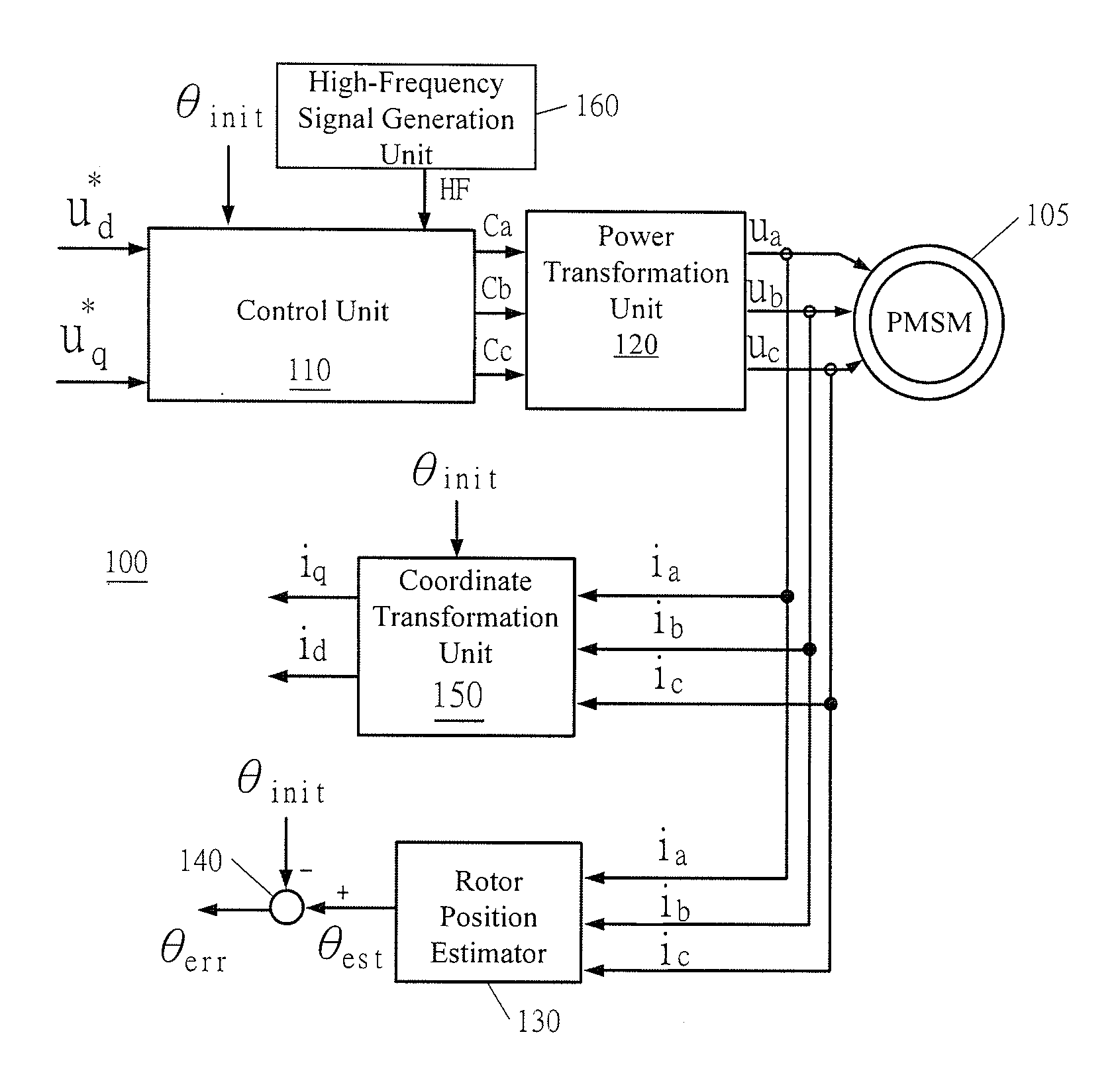
[0024]The present disclosure will be described in details in the following embodiments with reference to the accompanying drawings. However, the embodiments described are not intended to limit the present disclosure. Moreover, it is not intended for the description of operation to limit the order of implementation. Any device with equivalent functions that is produced from a structure formed by a recombination of elements shall fall within the scope of the present disclosure. Moreover, the appending drawings are only used for illustration and are not drawn to scale. For convenience of understanding, the same reference numbers represents the same elements in the following description.

[0025]The “about”, “approximately” or “substantially” used herein generally refer to a numeral error or scope within 20%, preferably within 10%, and more preferably within 5%. If it is not sated explicitly, the referred numbers are all regarded as approximate values with for example the error or scope re...


PUM


Abstract

An apparatus for measuring a position deviation of a rotor of a permanent magnet synchronous motor includes a control unit, a power transformation unit, a rotor position estimator and a calculation unit. The control unit receives a d-axis DC voltage signal and a q-axis AC voltage signal and receives an initial value of the rotor position and a high-frequency signal to output a three-phase command signal. The power transformation unit receives the three-phase command signal and outputs a three-phase control signal for controlling the motor. The rotor position estimator receives a three-phase current feedback signal corresponding to an operation of the motor and generates an estimation value of the rotor position. The calculation unit performs calculation to the initial value and the estimation value to generate a deviation value of the rotor position. Moreover, a method for measuring the position deviation is also disclosed herein.

Description

RELATED APPLICATIONS[0001]This application claims priority to Chinese Application Serial Number 201210486905.5, filed Nov. 26, 2012, which is herein incorporated by reference.BACKGROUND[0002]1. Technical Field[0003]The present disclosure relates to a permanent magnet synchronous motor, and more particularly relates to an apparatus for measuring a position of a rotor of a permanent magnet synchronous motor.[0004]2. Description of Related Art[0005]Generally, a brushless electric motor can be divided into a permanent magnet synchronous motor and a DC brushless motor according to different counter electromotive forces. Particularly, the permanent magnet synchronous motor has a sine-wave counter electromotive force, and can generate a constant torque through a sine-wave stator current.[0006]However, when the permanent magnet synchronous motor (PMSM) is operated, coupling thereof exists between a d-axis magnetic circuit and a q-axis magnetic circuit under a rotary coordinate system (d-q a...

Claims


Application Information

Patent Timeline
IPC IPC(8): H02P21/14
CPCH02P21/14H02P6/183H02P2203/11H02P21/18
Inventor ZHANG, JIA-MINLI, JIN-GENG
Owner DELTA ELECTRONICS INC
Learn More