Rotating electrical machine control device

a control device and electrical machine technology, applied in the direction of electronic commutators, motor/generator/converter stoppers, dynamo-electric converter control, etc., can solve problems such as estimation errors of magnetic flux, and achieve accurate calculation effects

Inactive Publication Date: 2014-05-29
AISIN AW CO LTD
View PDF15 Cites 25 Cited by
  • Summary
  • Abstract
  • Description
  • Claims
  • Application Information

AI Technical Summary

Benefits of technology

[0014]The processing delay time from the time when the operation of the voltage command is started to the time when the operation result is reflected on the voltage to be applied to the rotating electrical machine is a period that is 1.0 times the operation period, and the processing delay time generated by the voltage to be applied to the rotating electrical machine which changes in a stepped manner in every operation period is a period that is 0.5 times the operation period. The sum of thes...

Problems solved by technology

Such a phase shift in the coordinate transformation and a shift of the value resulting from the coordinate transformat...

Method used


Image

  • Rotating electrical machine control device
  • Rotating electrical machine control device
  • Rotating electrical machine control device

Examples


Embodiment Construction

[0028]An embodiment of the present invention will be described with reference to the accompanying drawings.

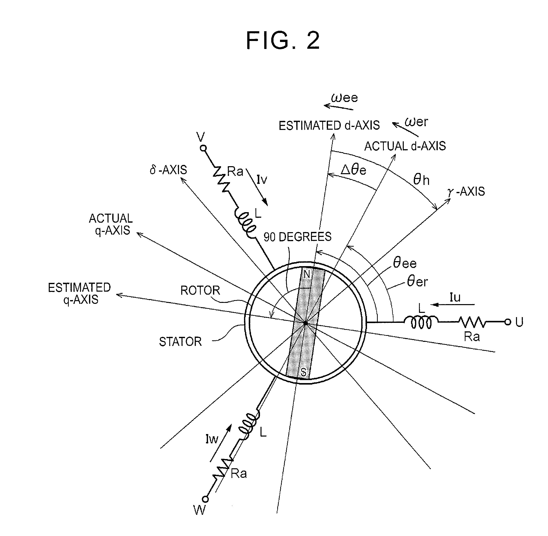
[0029]A rotating electrical machine MG has a rotor and a stator. The stator is fixed to a non-rotating member, and the rotor is rotatably supported radially inward of the stator. In the present embodiment, the rotating electrical machine MG is an interior permanent magnet synchronous motor (IPMSM) having permanent magnets embedded in a rotor, and has saliency. Electromagnets may be embedded instead of the permanent magnets.

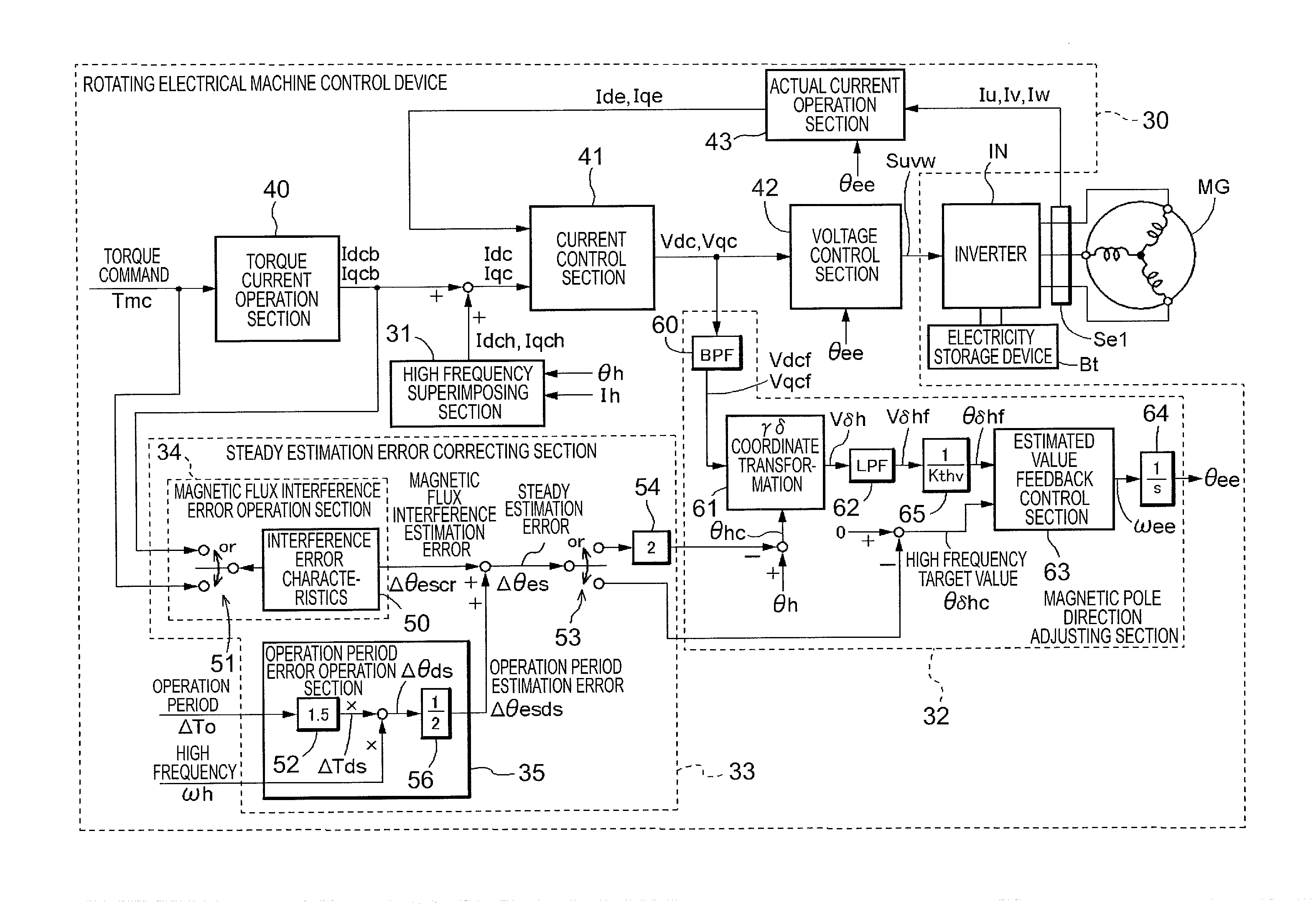
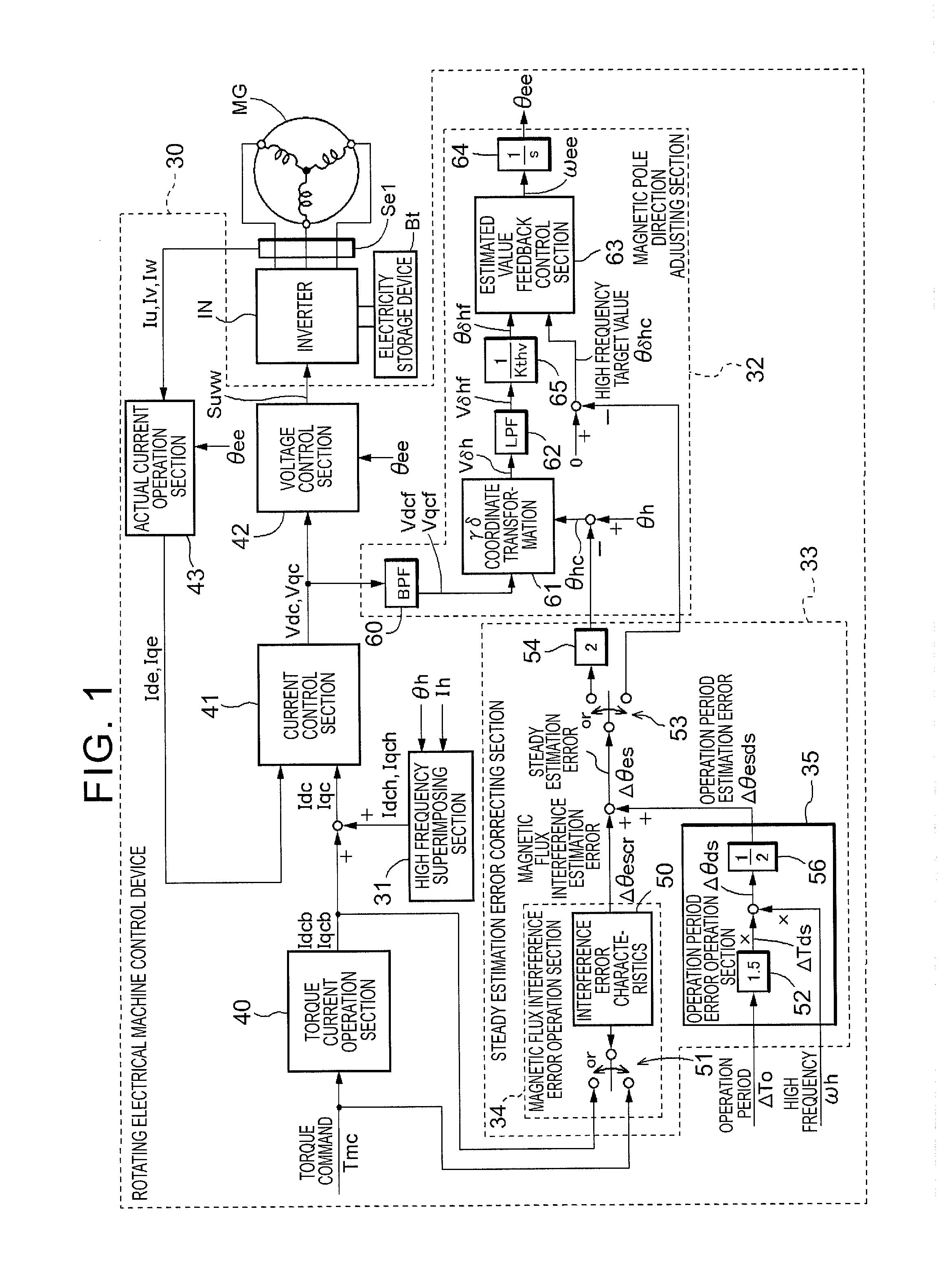
[0030]As shown in FIG. 1, three-phase coils included in the stator of the rotating electrical machine MG are electrically connected to an electricity storage device Bt as a direct-current (DC) power supply via an inverter IN that performs direct current-alternating current (DC-AC) conversion. The rotating electrical machine MG is capable of functioning as a motor (electric motor) that is supplied with electric power to generate power, and as a generator (elec...


PUM


Abstract

A rotating electrical machine control device that applies a high frequency current to a rotating electrical machine including a rotor having saliency, estimates a magnetic pole direction of the rotor on the basis of a high frequency component contained in a voltage command as a response component to the high frequency current, and controls the rotating electrical machine. A high frequency superimposing section sets an estimated d-q axis rotating coordinate system, and a magnetic pole direction adjusting section sets a high frequency coordinate system having a phase difference of the high frequency current command with respect to the estimated d-q axis rotating coordinate system. A steady estimation error correcting section calculates a magnetic flux interference estimation error as an error of the estimated value of the magnetic pole direction which is caused by the d-q axis magnetic flux interference.

Description

INCORPORATION BY REFERENCE[0001]The disclosure of Japanese Patent Application No. 2011-232067 filed on Oct. 21, 2011 including the specification, drawings and abstract is incorporated herein by reference in its entirety.BACKGROUND OF THE INVENTION[0002]The present invention relates to rotating electrical machine control devices that apply a high frequency current to a rotating electrical machine including a rotor having saliency, estimate the magnetic pole direction of the rotor on the basis of a high frequency component contained in a voltage command as a response component to the high frequency current, and control the rotating electrical machine.DESCRIPTION OF THE RELATED ART[0003]For example, a technique described in “Speed Control Method of Position Sensor less Salient-Pole PM Motor for Wide Speed Range Using High Frequency Current Injection” (Kazunori Yamada and two others, 2010, Proceedings of the Annual Conference of the Institute of Electrical Engineers of Japan, 4-356 to 3...

Claims


Application Information

Patent Timeline
IPC IPC(8): H02P6/18H02P6/06H02P6/08H02P6/17H02P6/182H02P6/28H02P21/00H02P21/13H02P21/14H02P21/18H02P21/22H02P21/24H02P21/28H02P23/14H02P27/04H02P27/08
CPCH02P21/24H02P21/18H02P6/183
Inventor SHIMADA, ARINORISAHA, SUBRATA
Owner AISIN AW CO LTD
Why Eureka
Try Eureka