Electrical Heating Device For Heating A Liquid, Method For Producing Same, And Use In The Electrical Simulation Of Nuclear Fuel Rods

a heating device and liquid technology, applied in the direction of ohmic resistance electrodes, heater elements, heating element materials, etc., can solve the problems of nuclear fuel rod sheath rupture, high thermal performance, and high thermal conduction. , to achieve the effect of reducing the thermal resistance of the interface and maximising the thermal conduction

Inactive Publication Date: 2014-06-05
COMMISSARIAT A LENERGIE ATOMIQUE ET AUX ENERGIES ALTERNATIVES
View PDF19 Cites 12 Cited by
  • Summary
  • Abstract
  • Description
  • Claims
  • Application Information

AI Technical Summary

Benefits of technology

[0027]The electrical heating device according to the invention, which can be termed indirect (the tubular resistor indirectly heating the liquid by thermal conduction through the intermediate element and the sheath), makes it possible to obtain a high thermal flow, up to several MW / m2, with the same metrological qualities that can be found on existing direct heating electrical simulation devices that have a high performance.
[0059]Finally, by virtue of the methods according to the invention, the interface thermal resistances are reduced by radial compression obtained by the restraining of the sheath on the whole device or by the thermal spraying of the various elements.

Problems solved by technology

It results in concrete terms in the abrupt degradation of the heat exchange between a heating wall and the heat-transfer fluid that surrounds it.
Thus, in a PWR reactor, the occurrence of this phenomenon could lead to the rupture of the nuclear fuel rod sheath.
However, modern nuclear fuel assemblies, in particular those intended to be used in PWR reactors, have more complex designs and higher thermal performance than those of the assemblies already tested, which tends to invalidate the normal qualification procedures in particular with regard to the appropriateness of the devices for electrical simulation of rods assembled in an assembly.
Thus the inventors have analysed that the modern holding grids that form high current diversions may cause rapid degradation of the electrical rod simulation devices of the direct heating type: the contact points created between the protrusions on the holding grid in question and a given rod are liable to generate an overintensity of current and therefore local electrolysis, sources of rapid degradation of the rods.
In fact, the inventors considered that the electrical simulation devices of the direct heating type could prevent the reliable qualification of the fuel assemblies.
Moreover, depending on the type of direct heating device necessary, the sheaths with a resistor function must be very thin in order to adapt their electrical resistance to the electrical supplies available, which is highly prejudicial to the service life of the simulation devices in question and to the possibility of reliably qualifying the assemblies.
In addition, the use of a direct-heating electrical simulation device involves electrical insulation thereof that is of high performance and reliable under the same operating conditions, which can take place only with complex technologies and materials that are expensive, but nevertheless fragile, and with a limited service life.
Finally, by definition, direct-heating electrical simulation devices cannot be used to qualify nuclear fuel assemblies intended to be immersed in an electrically conductive heat-transfer agent.
Since sodium intrinsically has high electrical conductivity, direct-heating electrical simulation devices will not be able to be used for said boiling tests for reactors (RNRs).
These devices are not satisfactory since they generate a non-homogeneous thermal flow in a backwash profile transversely to the sheath, that is to say an azimuth backwash profile.

Method used


Image

  • Electrical Heating Device For Heating A Liquid, Method For Producing Same, And Use In The Electrical Simulation Of Nuclear Fuel Rods
  • Electrical Heating Device For Heating A Liquid, Method For Producing Same, And Use In The Electrical Simulation Of Nuclear Fuel Rods
  • Electrical Heating Device For Heating A Liquid, Method For Producing Same, And Use In The Electrical Simulation Of Nuclear Fuel Rods

Examples


Embodiment Construction

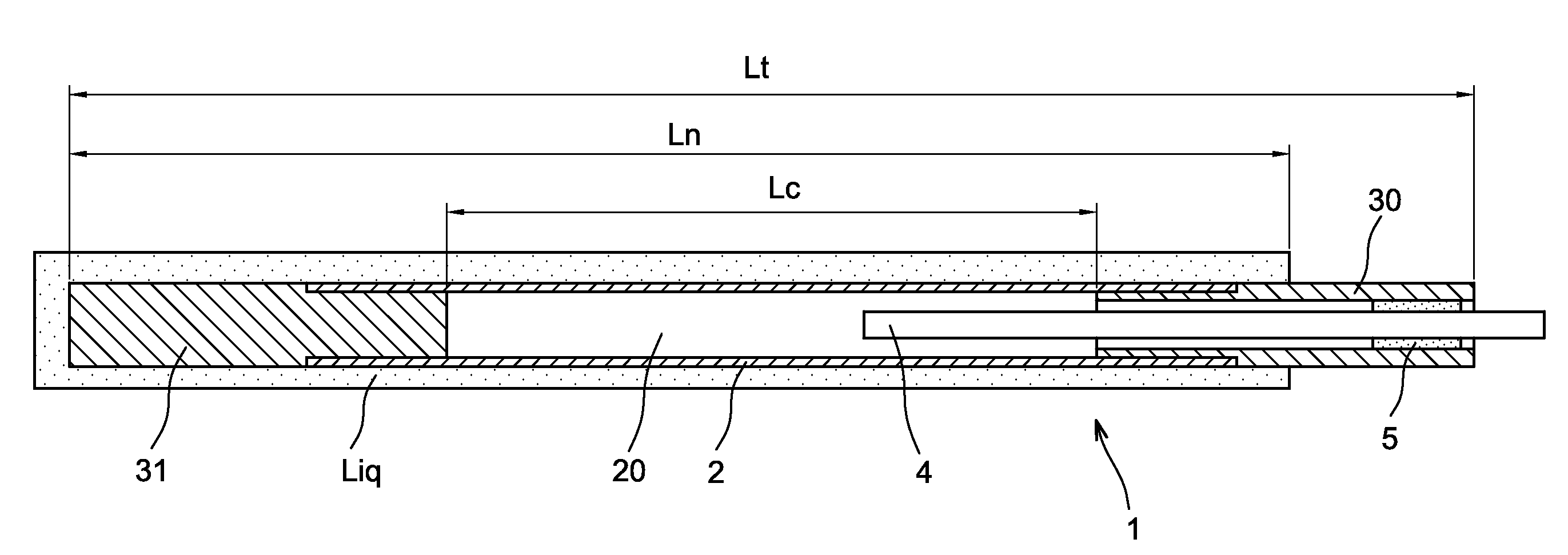
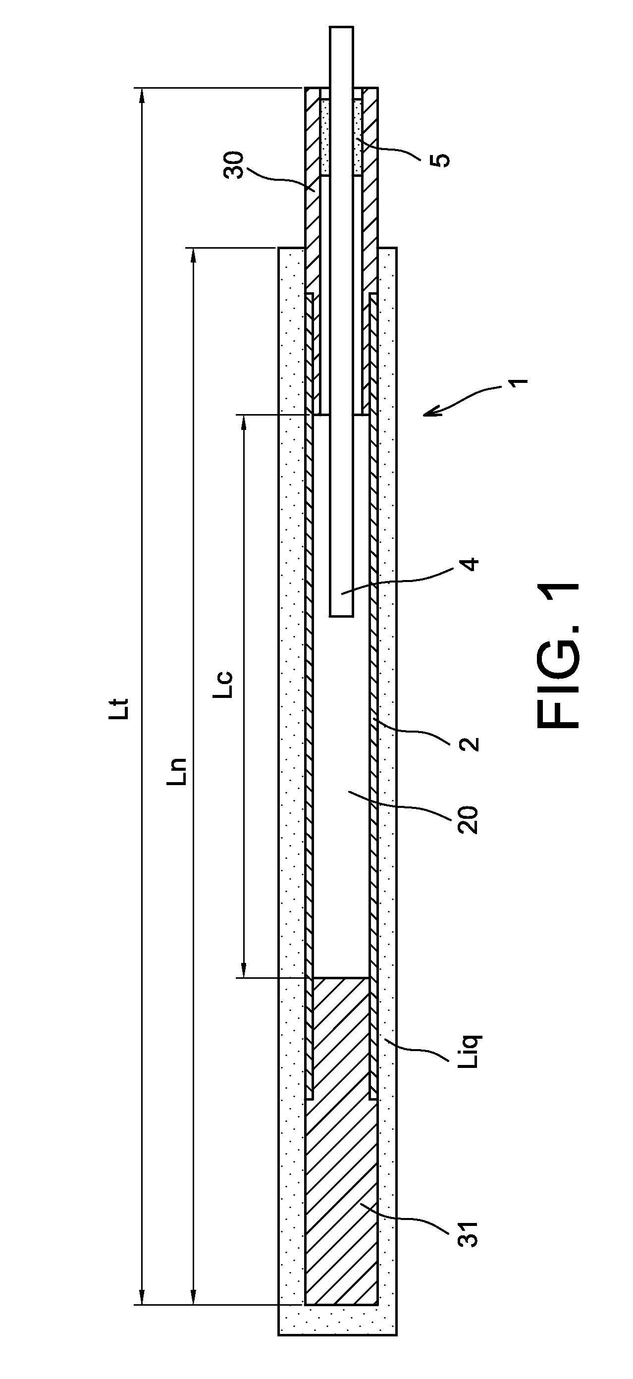
[0066]It is stated here that the electrical simulation devices according to the prior art (FIG. 1) and according to the invention (FIGS. 2 and 3) must make it possible to detect the occurrence of the boiling crisis, defined as a significant excursion in wall temperature for a small variation in the thermohydraulic control parameters.

[0067]It is also stated that, in all of FIGS. 1 to 3, the reference Lt, Ln and Lc designate respectively:[0068]Lt: overall length of the device;[0069]Ln: length of the device immersed in the liquid;[0070]Lc: heating length of the device.

[0071]It should be noted that the mounting of the electrical simulation device according to the prior art (FIG. 1) makes provision for immersing and electrical connection whereas the mounting of the electrical simulation device according to the invention (FIGS. 2 and 3) makes it possible to not immerse any electrical connection, which is advantageous since it is not necessary to effect a sophisticated electrical insulatio...


PUM

PropertyMeasurementUnit
temperatureaaaaaaaaaa
pressureaaaaaaaaaa
diameteraaaaaaaaaa

Abstract

A device for the electrical heating of a liquid with high thermal flow, according to which the resistor in tubular form and supplied with direct current can indirectly heat the liquid by conduction through an electrically insulating and thermally conductive intermediate element that surrounds it with direct mechanical contact, the assembly consisting of tubular resistor and intermediate element being jacketed by a sheath intended to be immersed, over at least a major part of the length thereof, in the liquid to be heated. The preferred application is the electrical simulation of nuclear fuel rods intended to be assembled in power reactors, of the PWR but also RNR-Na type.

Description

TECHNICAL FIELD[0001]The invention concerns a novel device for the electrical heating of a liquid with high thermal flow.[0002]The main application of the invention is the production of a novel device for the electrical simulation of nuclear fuel rods intended to be assembled in assemblies by holding grids and intended to be used in so-called power reactors, and more particularly pressurised water reactors (abbreviated to PWR). As described precisely below, the use of such a device enables the thermohydraulic qualification of fuel rods by detecting the occurrence of the boiling crisis of the liquid in which they are intended to be immersed.[0003]The invention aims in general terms to increase the service life and quality of the existing heating devices with high thermal flow, in particular the qualification of devices for the electrical simulation of nuclear fuel rods currently existing with high thermal flows.[0004]Although described with reference to the main application, the devi...

Claims


Application Information

Patent Timeline
Patent Type & Authority Applications(United States)
IPC IPC(8): H05B1/02G21C17/06H01C17/02H05B3/44H05B3/03
CPCH05B1/0244G21C17/06H05B3/44H05B3/03H01C17/02G21C17/001G21C21/02H05B3/78Y02E30/30Y10T29/49083G21C17/00H05B3/42
Inventor GROS D'AILLON, LUCCUBIZOLLES, GERAUD
Owner COMMISSARIAT A LENERGIE ATOMIQUE ET AUX ENERGIES ALTERNATIVES
Why Eureka
Try Eureka