Eureka AIR delivers breakthrough ideas for toughest innovation challenges, trusted by R&D personnel around the world.

Pilot design for universal frequency reuse in cellular orthogonal frequency-division multiplexing systems

a frequency-division multiplexing and pilot technology, applied in the field of transmission information, can solve the problems of difficult to estimate channel parameters and difficulty in achieving frequency reuse of one, and achieve the effect of minimizing co-channel interference and maximizing throughpu

Active Publication Date: 2014-06-05
MARVELL ASIA PTE LTD
View PDF5 Cites 3 Cited by
  • Summary
  • Abstract
  • Description
  • Claims
  • Application Information

AI Technical Summary

Benefits of technology

This patent is about a system and method for transmitting information wirelessly while minimizing interference and maximizing throughput. The system includes a source and a receiver. The source broadcasts separate signals for data and pilot sequences, which serve as channel information. These signals are transmitted over distinct bands of frequency. To avoid interference, the pilot and data subcarriers are broadcasted with different factors of frequency reuse. This compromises true universal frequency reuse, but allows for better estimation of the channel. The technical effect of this patent is improved wireless communication reliability without wasting throughput in a network.

Problems solved by technology

However, in wireless systems it is challenging to achieve a frequency reuse of one because of the co-channel interference presented by the sources of adjacent cells.
This requisite knowledge presents a problem for cellular communication systems—achieving a frequency reuse of one results in co-channel interference that makes it harder to estimate the parameters of the channel, while using a multi-carrier modulation scheme such as OFDM to eliminate the co-channel interference requires knowing the parameters of the channel.

Method used


Image

  • Pilot design for universal frequency reuse in cellular orthogonal frequency-division multiplexing systems
  • Pilot design for universal frequency reuse in cellular orthogonal frequency-division multiplexing systems
  • Pilot design for universal frequency reuse in cellular orthogonal frequency-division multiplexing systems

Examples


Embodiment Construction

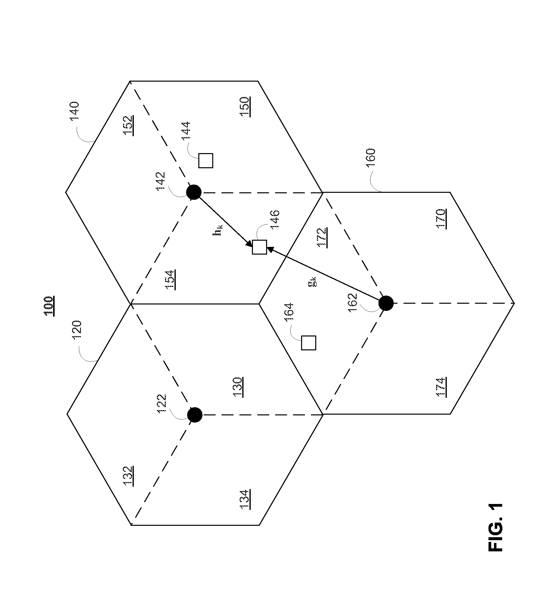
[0027]FIG. 1 shows a simplified diagram of illustrative cellular system 100. Cellular system 100 can include a plurality of base stations that are interconnected to form a mobile or cellular network. These base stations can include base stations 122, 142, and 162. Each of these base stations can be configured to communicate with mobile stations located within a particular physical area within that base station's radio communications range. The physical area may be referred to as a radio cell. In particular, base station 122 may communicate with mobile stations within radio cell 120, base station 142 may communicate with mobile stations within radio cell 140 (e.g., mobile stations 144 and 146), and base station 162 may communicate with mobile stations within radio cell 160 (e.g., mobile station 164). In FIG. 1, radio cells 120, 140, and 160 are represented by hexagonal regions, although this shape is merely illustrative.

[0028]Mobile stations 144, 146, and 164 may be any suitable type...


PUM


Abstract

Systems and methods are provided for transmitting information between an intended source and a receiver to minimize co-channel interference from at least one interfering source. Pilot subcarriers and data subcarriers may be broadcast from an intended source and at least one interfering source. The pilot subcarriers may be shared across base stations or distributed among base stations in frequency, in time, or both. In addition, the frequency reuse factor of the pilot subcarriers may be different than the frequency reuse factor of the data subcarriers A receiver receives a composite signal that corresponds with an intended signal from an intended source and an interfering signal from at least one interfering source. The portion of the received signal that corresponds to the intended signal may be recovered by the receiver based on the broadcast of the pilot subcarriers.

Description

CROSS-REFERENCE TO RELATED APPLICATIONS[0001]This claims the benefit under 35 U.S.C. §119(e) of U.S. Provisional Application No. 60 / 955,948 filed Aug. 15, 2007, which is hereby incorporated herein by reference in its entirety.BACKGROUND[0002]The following relates generally to transmitting information between an intended source and a receiver in a communication system, and more particularly to designs for frequency reuse and pilot subcarriers to minimize co-channel interference during transmission from other sources that cause interference.[0003]There are several conventional techniques to increase the throughput of a wireless network. These techniques aim to expand the amount of information that can be transmitted over the network while minimizing the probability that errors will occur during transmission. One of these techniques is frequency reuse, which entails using the same frequency on a network for multiple simultaneous transmissions. Most wireless communication systems are de...

Claims


Application Information

Patent Timeline
Patent Type & Authority Applications(United States)
IPC IPC(8): H04L25/03H04W16/02H04L5/00
CPCH04L25/03821H04W16/02H04L5/005H04L5/0007H04L5/0021H04L5/0039H04L5/0051H04L5/0062H04L5/0082H04L5/0083H04L25/0204H04L25/0226H04L27/2613
Inventor LEE, JUNGWONLOU, HUI-LING
Owner MARVELL ASIA PTE LTD
Why Eureka
Eureka Blog
Learn More