Inter-integrated circuit-slave interface, and method for operating an inter-integrated circuit-slave interface

a technology of inter-integrated circuits and interfaces, applied in the direction of synchronisation information channels, digital transmission, synchronous/start-stop systems, etc., can solve the problems of no more than a compromise, unsatisfactory interactions, etc., and achieve the effect of simple and cost-effectiv

Active Publication Date: 2014-06-05
ROBERT BOSCH GMBH
View PDF5 Cites 2 Cited by
  • Summary
  • Abstract
  • Description
  • Claims
  • Application Information

AI Technical Summary

Benefits of technology

[0024]Using the example device of the present invention and / or the example method of the present invention, it is advantageously possible to solve the two afore-described problems, in particular, and to solve them separately of each other. In addition, it is possible to filter transients from the clock signal and / or the data input signal.
[0025]Another advantage is that the example device of the present invention is able to be produced in a simple and cost-effective manner in the form of a modular component, and that adaptations may be made in an uncomplicated manner by way of programming.

Problems solved by technology

Undesired interactions may arise if multiple slave units are connected to an interface.
In particular, it may happen that a certain slave unit erroneously interprets a response of another slave unit as a start signal of the master unit, but it may also be the case that other slave units erroneously interpret the response of the particular slave unit as a start signal of the master unit.
However, a disadvantage of this approach is that the parameters of the two delay elements, i.e., the delay times of the transition times, have different effects on the two afore-described problems, so that instead of an optimal solution, no more than a compromise is achievable when using merely two delay elements.

Method used


Image

  • Inter-integrated circuit-slave interface, and method for operating an inter-integrated circuit-slave interface
  • Inter-integrated circuit-slave interface, and method for operating an inter-integrated circuit-slave interface
  • Inter-integrated circuit-slave interface, and method for operating an inter-integrated circuit-slave interface

Examples


Embodiment Construction

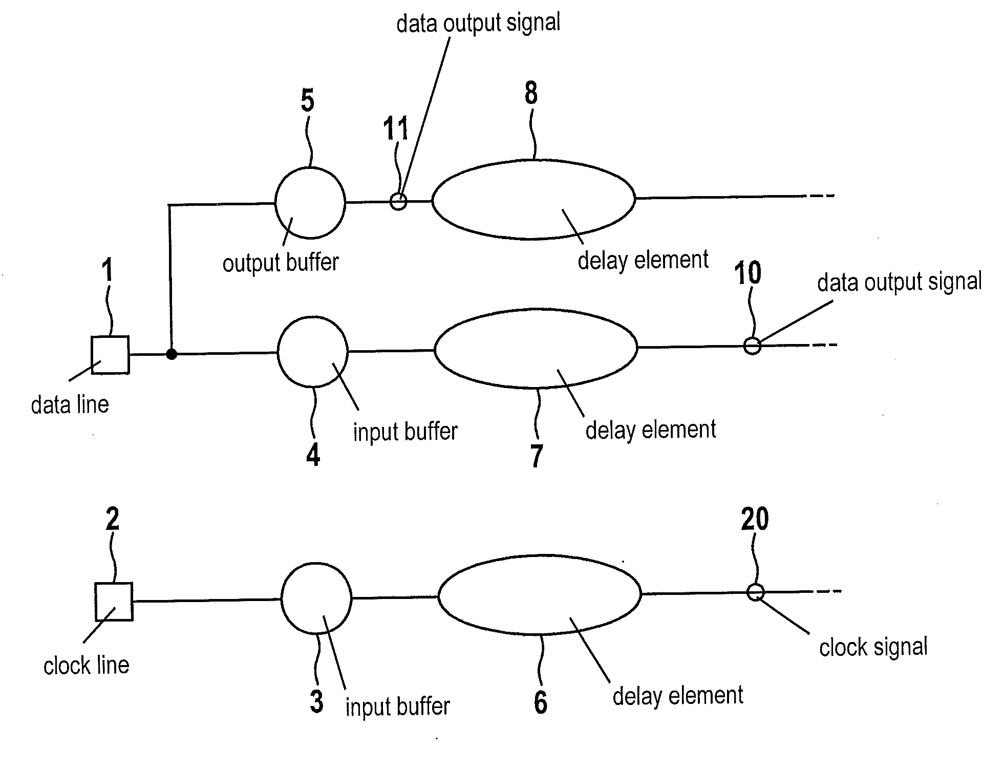
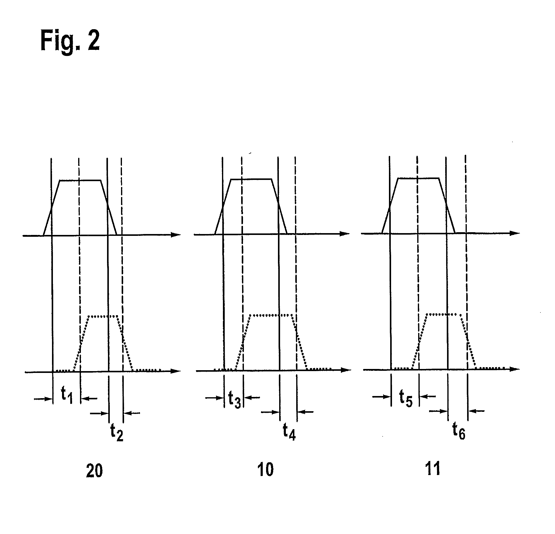
[0028]The present invention is described with reference to special developments and with reference to the attached figures, but the present invention is not limited to these example embodiments and figures. The figures are not to be interpreted in limiting form. For illustrative purposes, certain elements in the figures may be shown in enlarged or exaggerated form and not true to scale.

[0029]If not specifically stated otherwise, the use of an indefinite or definite article with reference to a word in the singular, e.g., “a”, “of a”, “the”, also encompasses the plural of such a word. The designations “first”, “second” etc. in the description and in the claims are used to distinguish similar or identical elements to be differentiated and not necessarily to describe a temporal or other sequence. The terms used in this way are basically to be considered exchangeable under corresponding conditions. FIG. 1 schematically shows an advantageous specific example embodiment of the interface ac...


PUM


Abstract

An I2C interface is provided which has a data line and a clock line, the clock line having a first input buffer, and the data line having a second input buffer and an output buffer, the data line being provided for the transmission of a data input signal and a data output signal, the clock line being provided for the transmission of a clock signal, the clock line having a first delay element, and the data line having a second delay element and a third delay element. A method for operating an I2C slave interface is also provided.

Description

CROSS REFERENCE[0001]The present application claims the benefit under 35 U.S.C. §119 of German Patent Application No. DE 102012222357.6 filed on Dec. 5, 2012, which is expressly incorporated herein by reference in its entirety.BACKGROUND INFORMATION[0002]Inter-integrated circuit interfaces, hereinafter also referred to as I2C interfaces, via which a clock generator device, also referred to as master unit or, master, is able to communicate with multiple slave units in serial manner are available. The master transmits a clock signal by way of a clock line, and a data input signal and a data output signal are transmitted via a bidirectional data line. The data line and the clock line are able to be pulled from a low potential (low level) to a high potential (high level), these potentials corresponding to two logic states. The start of a data transmission and the end of a data transmission, and the data as such are encoded by defined states or state changes on the data line with respect...

Claims


Application Information

Patent Timeline
Patent Type & Authority Applications(United States)
IPC IPC(8): H04L7/00
CPCH04L7/0041H04L7/0008H04L7/0037
Inventor CVEJANOVIC, DORDE
Owner ROBERT BOSCH GMBH
Why Eureka
Try Eureka