Fuel component and method of manufacturing of a fuel component

a technology of fuel components and manufacturing methods, applied in the field of fuel components, can solve the problems of affecting the production efficiency of local power, affecting the quality of local power, and requiring vacuum on the surface of fuel components, etc., and achieve the effect of improving properties

Inactive Publication Date: 2014-06-05
WESTINGHOUSE ELECTRIC SWEDEN
View PDF2 Cites 2 Cited by
  • Summary
  • Abstract
  • Description
  • Claims
  • Application Information

AI Technical Summary

Benefits of technology

[0009]The object of the present invention is to provide a fuel component with improved properties.

Problems solved by technology

Known methods for coating neutron absorbing material on the surface of fuel components comprise sensitive processes that require vacuum and are expensive.
Another problem with a layer of an absorbing material is to assure that the layer of the neutron absorbing material remains on the surface of the fuel component.
The transition from room temperature to high temperatures between the fuel cycles creates stresses between material with different thermal and elastic properties, wherein the layer of neutron absorbing material can crack and fall off.
If the layer of neutron absorbing material on the fuel component entirely or partly is missing or if the neutron absorbing material has been displaced within the fuel rod, for example during reactor operation, the produced power in the fuel element is affected, which results in that the produced power locally can exceed permitted values.
It may be necessary to stop the reactor and exchange fuel element with the defective fuel components, which results in great losses in form of missing energy production and costs for repairing of the fuel element.
At minor fuel failures, the outer surrounding is contaminated mainly by gases formed during the fission process.
A contamination of the outer surrounding can result in maintenance personal at the reactor being exposed to increased irradiation doses at maintenance work.
Fuel failures result in great costs in form of lacking production at operational stop and by costs for repairing the failing fuel element.

Method used


Image

  • Fuel component and method of manufacturing of a fuel component
  • Fuel component and method of manufacturing of a fuel component
  • Fuel component and method of manufacturing of a fuel component

Examples


Embodiment Construction

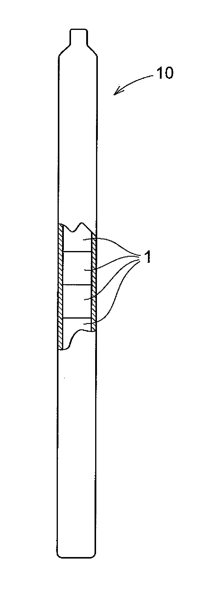
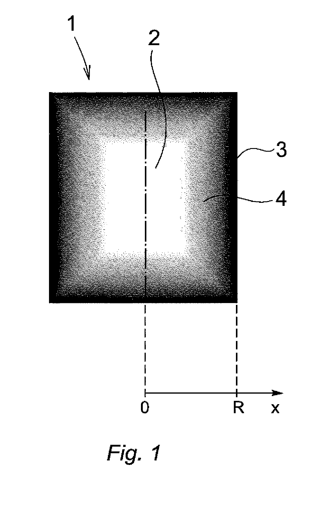
[0043]FIG. 1 discloses an example of a fuel component 1, in the following denoted the component, according to an embodiment of the invention in a cross-section view seen from the side. The component 1 in FIG. 1 has a cylindrical shape, with the centre of the base of the cylinder in 0 and the envelop surface of the cylinder at R, along an x-axis. Also other shape of the component 1 are possible such as rectangular, square, spherical, etc.

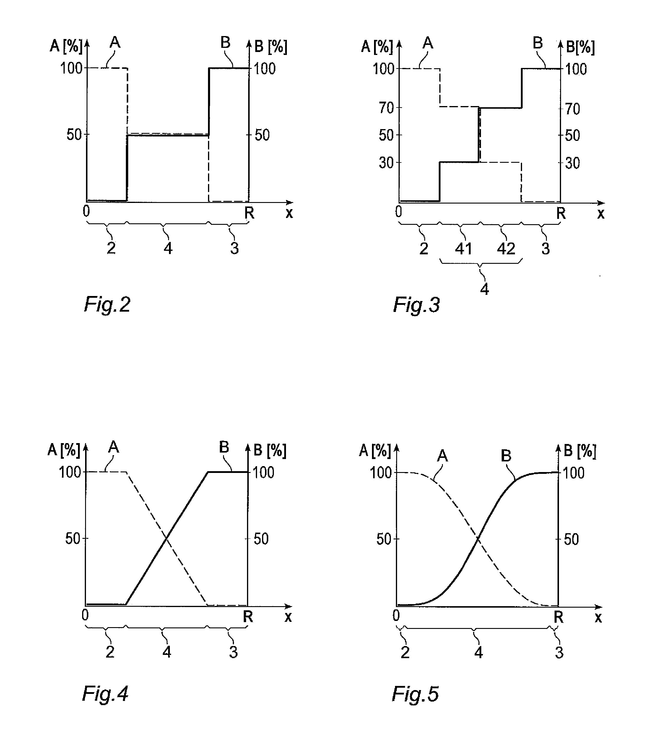
[0044]The component 1 is adapted to be used in fission reactors and comprises a core 2 consisting of a first material and a layer 3 consisting of a second material. The core 2 of the component comprises a fissile material adapted to generate energy and neutrons, in such a way that the nuclear reaction in a fission reactor can be maintained. The layer 3 of the component encloses, in the example disclosed in FIG. 1, completely the core 2 and protects the core 2 from an outer surrounding by its protecting properties, such as corrosion resistance and imp...


PUM

PropertyMeasurementUnit
temperaturesaaaaaaaaaa
concentrationaaaaaaaaaa
corrosion resistantaaaaaaaaaa

Abstract

The invention relates to a fuel component and a method for manufacturing of a fuel component. The fuel component is adapted to be used in fission reactors. The fuel component comprises a core consisting of a first material, and a layer consisting of a second material. The layer encloses at least partly the core. The first material comprises a fissile substance. The fuel component comprises an intermediate layer between the core and the layer. The intermediate layer has a material gradient that comprises a decrease of the concentration of the first material from the core to the layer and an increase of the concentration of the second material from the core to the layer.

Description

TECHNICAL FIELD[0001]The present invention relates to a fuel component adapted to be used in fission reactors, comprising a core consisting of first material, and a layer consisting of a second material, wherein the layer at least partly encloses the core, wherein the first material comprises a fissile substance.[0002]The present invention relates also to a method for manufacturing of a fuel component according to the above.BACKGROUND[0003]Nuclear fuel for fission reactors comprises fuel components containing a fissile substance, such as U-235. The fuel components need to be protected from interaction from an outer surrounding. In boiling water reactors and pressure water reactors the fuel component is completely enclosed in corrosion resistant cladding tubes of a zirconium alloy with a low neutron absorption cross-section. The function of the cladding tubes is to enclose the fuel components and thereby prevent interaction between an outer surrounding and the fissile substance. The ...

Claims


Application Information

Patent Timeline
Patent Type & Authority Applications(United States)
IPC IPC(8): G21C3/04
CPCG21C3/04B22F3/1039B22F5/12B22F7/008B22F2999/00C04B35/6455C04B37/021C04B2235/666C04B2235/75C04B2237/34C04B2237/343C04B2237/348C04B2237/36C04B2237/365C04B2237/368C04B2237/40C04B2237/401C04B2237/402C04B2237/403C04B2237/405C04B2237/408C04B2237/58C04B2237/84C22C1/058C23C24/08G21C3/02G21C21/02Y02E30/30B22F3/20B22F2207/01B22F7/00C23C12/00B22F7/02G21C3/06G21C21/04
Inventor HALLSTADIUS, LARSBACKMAN, KARINREBENSDORFF, BJORNWIDEGREN, HANS
Owner WESTINGHOUSE ELECTRIC SWEDEN
Why Eureka
Try Eureka