
Eureka
For R&D, Eureka makes reading and utilizing patents & technical documents easy.
Eureka AIR
Designed for self-driven R&D workflows. Generate viable solutions, solve complex R&D challenges, empower your innovation with AI.

Eureka Materials
Designed for material experts only. Revolutionize your material R&D, from search, analyze, to developing new materials.

TechResearch
Generate reliable direction feasibility study reports for your R&D in just a few steps.

TechSeek
Discover and master advanced knowledge NOW. Basics, ideas, possibilities, all at once.

TechMind
As an expert in R&D Theories, TechMind can generates customized viable solutions instantly.

TechRisk
Analyze your overall solution with one click, know your potential R&D risks in advance.

TechMonitor
Get weekly tech updates, stay abreast of the latest tech innovations and key insights.
Sound reproduction device
- Summary
- Abstract
- Description
- Claims
- Application Information
AI Technical Summary
Benefits of technology
Problems solved by technology
Method used
Image

Examples
exemplary embodiment 1
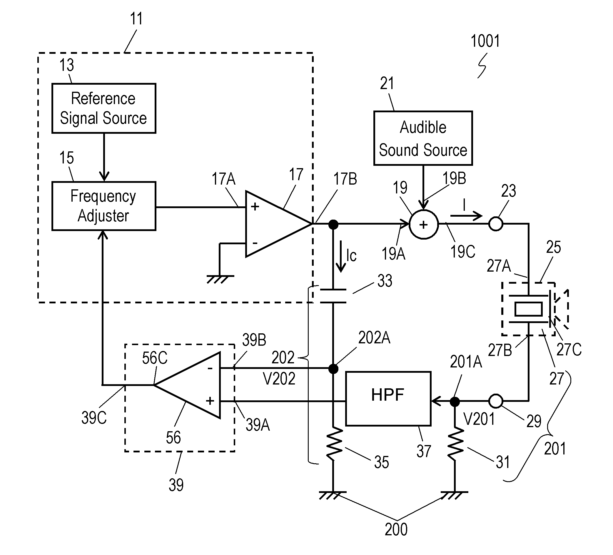
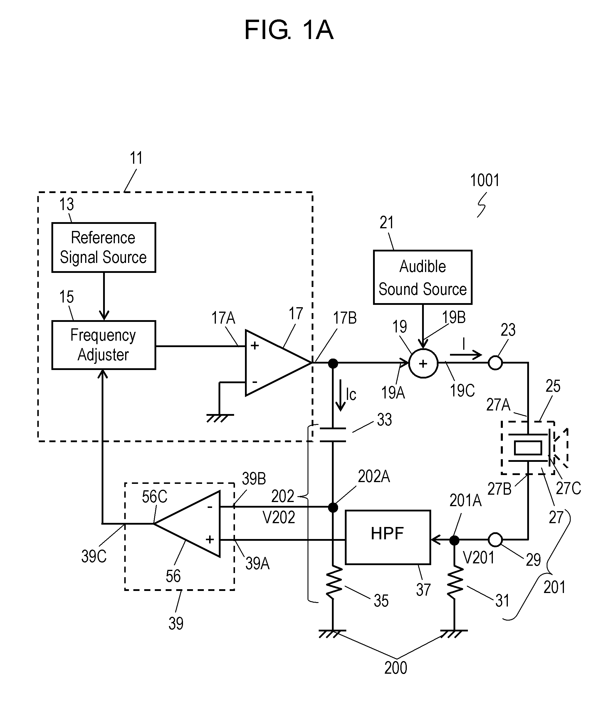
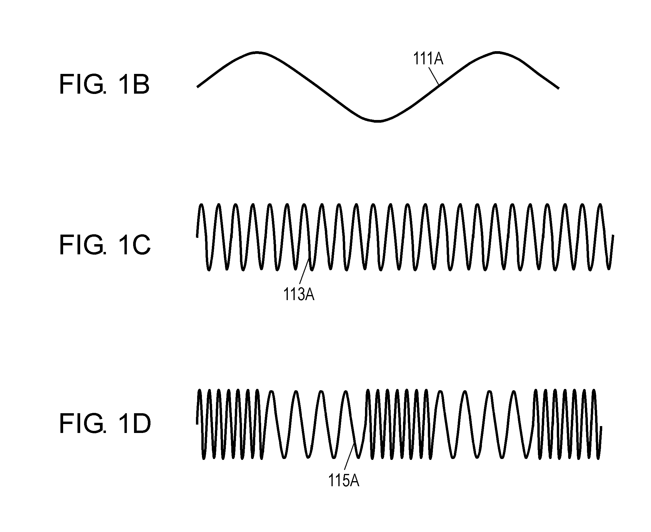
[0021]FIG. 1A is a circuit block diagram of sound reproduction device 1001 according to Exemplary Embodiment 1 of the present invention. FIGS. 1B to FIG. 1D show signals of sound reproduction device 1001. Sound reproduction device 1001 includes ultrasonic wave source 11, modulator 19, audible sound source 21, super-directivity loudspeaker 25, current detectors 31 and 35, high-pass filter (HPF) 37, and differential amplifier unit 39. Ultrasonic wave source 11 is configured to output a carrier wave signal having a frequency in an ultrasonic band, and includes reference signal source 13 for generating and outputting a reference frequency, frequency adjuster 15 connected electrically to reference signal source 13, and amplifier 17 connected to frequency adjuster 15. Based on the reference frequency, frequency adjuster 15 outputs a carrier wave signal having a frequency in the ultrasonic band that is necessary to drive piezoelectric element 27 of super-directivity loudspeaker 25. The car...
exemplary embodiment 2
[0049]FIG. 4 is a circuit block diagram of sound reproduction device 1002 according to Exemplary Embodiment 2 of the present invention. In FIG. 4, components identical to those of sound reproduction device 1001 according to Embodiment 1 shown in FIG. 1A are denoted by the same reference numerals. Sound reproduction device 1002 according to Embodiment 2 further includes temperature sensors 51 and 53, and temperature compensator 55.
[0050]Temperature sensor 51 is disposed as close to piezoelectric element 27 of super-directivity loudspeaker 25 as possible. Temperature sensor 51 outputs an ambient temperature around super-directivity loudspeaker 25, while the ambient temperature of super-directivity loudspeaker 25 is substantially equal to an ambient temperature around piezoelectric element 27 since piezoelectric element 27 is installed into super-directivity loudspeaker 25. An output of temperature sensor 51 is piezoelectric element temperature Tp that is the ambient temperature of pie...
exemplary embodiment 3
[0071]FIG. 5 is a circuit block diagram of sound reproduction device 1003 according to Exemplary Embodiment 3 of the present invention. In FIG. 5, components identical to as those of sound reproduction devices 1001 and 1002 according to Embodiments 1 and 2 shown in FIGS. 1A and 4.
[0072]In sound reproduction device 1003 according to Embodiment 3, super-directivity loudspeaker 25 and capacitor 33 are mounted on same single circuit board 57. Both super-directivity loudspeaker 25 and capacitor 33 are disposed as close to each other as possible.
[0073]Temperature sensor 59 is disposed to circuit board 57. Temperature sensor 59 is disposed at a position as close to both super-directivity loudspeaker 25 and capacitor 33 as possible on circuit board 57. Super-directivity loudspeaker 25 and capacitor 33 are located close to each other and mounted on the same circuit board 57 to be thermally coupled through circuit board 57, thereby causing temperatures of super-directivity loudspeaker 25 and ...
PUM
 Abstract
Description
Claims
Application Information
 - R&D Engineer
- R&D Manager
- IP Professional
- Industry Leading Data Capabilities
- Powerful AI technology
- Patent DNA Extraction
Browse by: Latest US Patents, China's latest patents, Technical Efficacy Thesaurus, Application Domain, Technology Topic, Popular Technical Reports.
© 2024 PatSnap. All rights reserved.Legal|Privacy policy|Modern Slavery Act Transparency Statement|Sitemap|About US| Contact US: help@patsnap.com