
Dual protection cap for bolt and nut

Inactive Publication Date: 2014-06-12
KIM LEE NAM +1
View PDF10 Cites 16 Cited by
  • Summary
  • Abstract
  • Description
  • Claims
  • Application Information

AI Technical Summary

Benefits of technology

The present invention relates to a dual protection cap for a bolt and a nut which increases productivity and reduces production costs. The cap is made of synthetic resin and has an insertion groove and protrusion piece to securely couple the outer and inner caps. The inner cap is compulsorily inserted to prevent damage to the bolt by contraction and hardening. When a bolt is damaged or disjointed, the fixed piece can be easily separated from the bolt and reused. The cap prevents the nut from being loosened by vibration and provides a long-term rust prevention effect. The fiber packing in the cap also prevents grease from leaking and adjusts moisture to prevent rusting. The cap has elasticity to expand and protect the bolt cap from damage caused by heat.

Problems solved by technology

However, because the above-described conventional protection cap for a bolt and a nut is generally made of a plastic material or a rubber material, when an organic chemical material is exposed at sunlight in view of a characteristic of a plastic or rubber material, an organic chemical component is volatilized to be stiffly hardened and deteriorated and thus there is a problem that the conventional protection cap is easily damaged by an external pressure.
Particularly, when a temperature rises in a summer season, if a bolt and a nut, which are a metal component expand by a heat, in a state in which a protection cap having different expansion coefficients is deteriorated and hardened, there is a problem that the protection cap does not withstand expansion of the bolt and the nut and is damaged.
As described above, when a protection cap for a bolt and a nut is damaged, the protection cap loses a function of maintaining airtightness from the outside, and thus there is a problem that the bolt and the nut are oxidized by rainwater or moisture.

Method used


Image

  • Dual protection cap for bolt and nut
  • Dual protection cap for bolt and nut
  • Dual protection cap for bolt and nut

Examples


Embodiment Construction

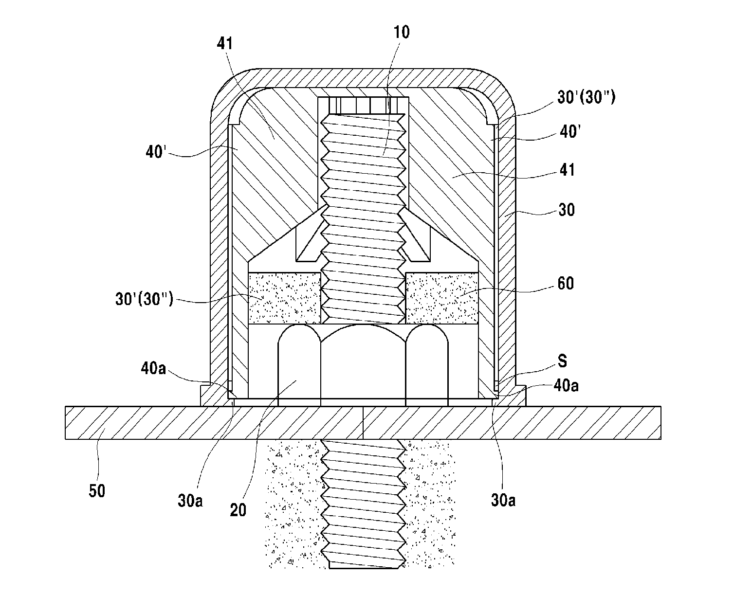
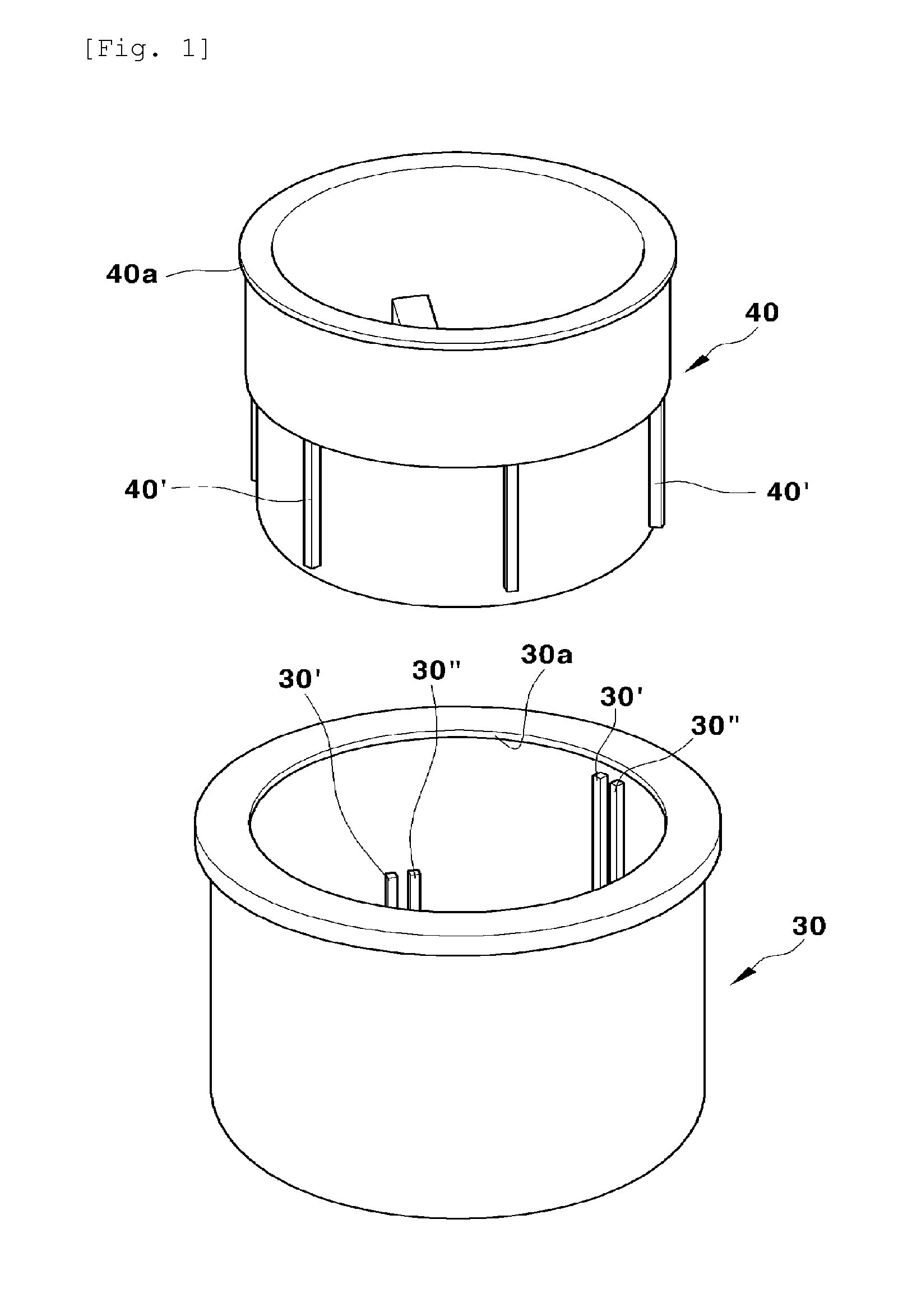
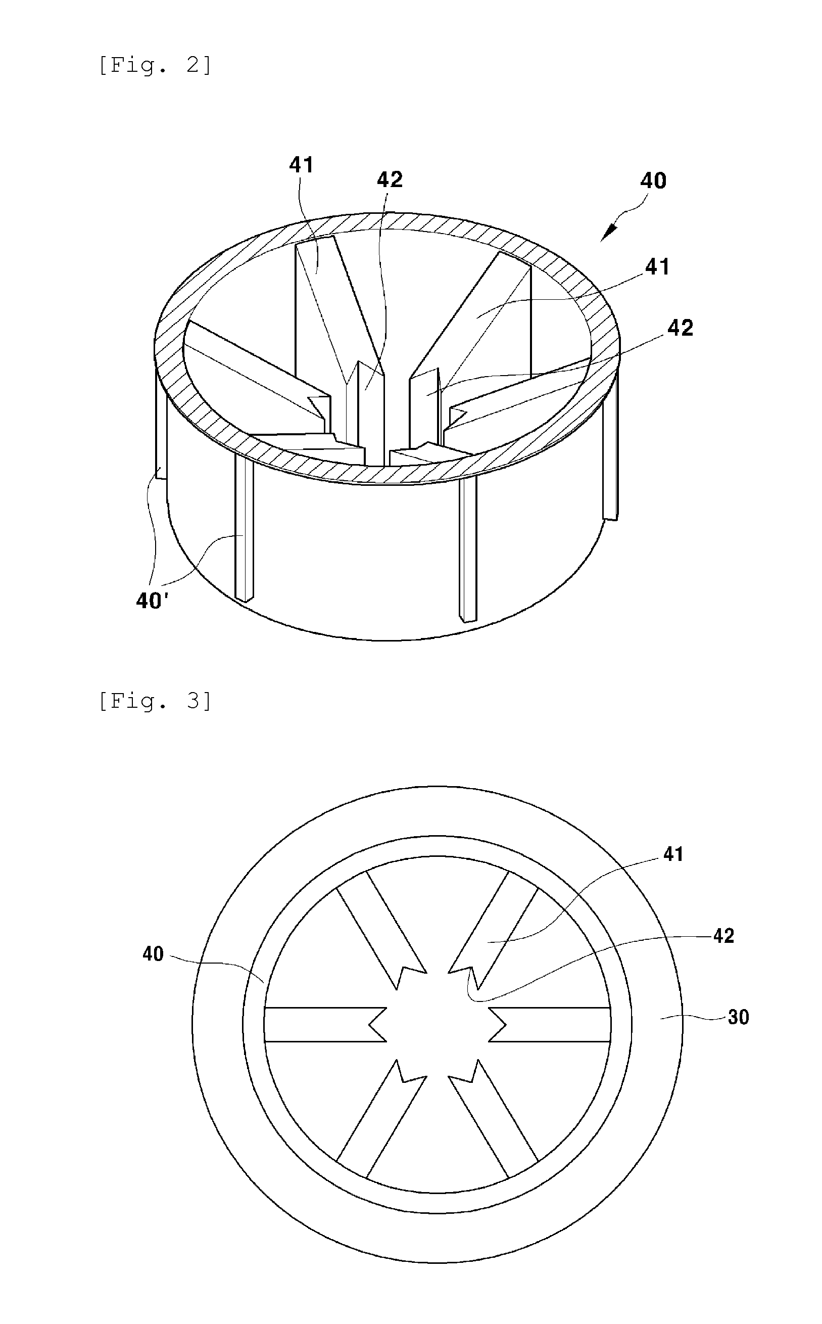
[0031]Before describing the present invention, the accompanying drawings for helping comprehension of technology are as follows. FIG. 1 is an exploded perspective view illustrating a configuration of a dual protection cap for a bolt and a nut according to an exemplary embodiment of the present invention, FIG. 2 is a partially cut-away perspective view illustrating a configuration of a dual protection cap for a bolt and a nut according to an exemplary embodiment of the present invention, FIG. 3 is a top plan view illustrating a configuration of a dual protection cap for a bolt and a nut according to an exemplary embodiment of the present invention, FIG. 4 is a cross-sectional view illustrating a configuration of a dual protection cap for a bolt and a nut according to an exemplary embodiment of the present invention, FIG. 5 is a cross-sectional view illustrating a configuration of a dual protection cap for a bolt and a nut and a coupling state between a bolt and a nut according to an ...


PUM


Abstract

The present invention pertains to a dual protection cap for a bolt and a nut. The present invention relates to a protection cap for a bolt and a nut, which is open at one side and covers a bolt and a nut so as to separate the same from the outside, and comprises: an outer cap and an inner cap are respectively injection molded with synthetic resin; fitting grooves, which are formed on the inside of the outer cap at a uniform interval in a longitudinal direction, are fitted and coupled with protrusion pieces, which are formed to protrude from the outer periphery of the inner cap at a uniform interval in a longitudinal direction; and triangular protrusion pieces are formed on the end portion of each of fixing pieces, which radially protrude from the peripheral surface of the bottom surface in the inner cap.

Description

CROSS-REFERENCE TO RELATED APPLICATION[0001]This application claims the benefit of Korean Patent Application No. 10-2011-0023368, filed on Mar. 16, 2011 in the Korean Intellectual Property Office, the disclosure of which is incorporated herein by reference.TECHNICAL FIELD[0002]The present invention relates to a dual protection cap for a bolt and a nut.BACKGROUND ART[0003]In general, a protection cap for a bolt and a nut is a bolt and nut interception member inserted into bolt and nut portions to prevent the bolt and the nut from oxidizing and to improve a stiff atmosphere of the bolt and the nut.[0004]Such a conventional dual protection cap for a bolt and a nut is generally formed in a cap shape having opened one side that covers and protects an outer protruded portion of a bolt and a nut formed to fasten and fix a base plate that supports a structure such as a streetlight or a soundproof wall to the ground.[0005]More specifically, a conventional protection cap for a bolt and a nut ...

Claims


Application Information

Patent Timeline
IPC IPC(8): F16B37/14
CPCF16B37/14F16B37/005
Inventor KIM, LEE NAMJIN, JAE HO
Owner KIM LEE NAM
Learn More