Polishing pad

Inactive Publication Date: 2014-06-19
TORAY IND INC
View PDF2 Cites 8 Cited by
  • Summary
  • Abstract
  • Description
  • Claims
  • Application Information

AI Technical Summary

Benefits of technology

[0014]In accordance with the present invention, it is possible to provide a polishing pad wh

Problems solved by technology

However, a corner portion in a cross-sectional shape of the groove, or burrs formed at the corner portion resulting f

Method used


Image

  • Polishing pad
  • Polishing pad
  • Polishing pad

Examples


Example

Example 1

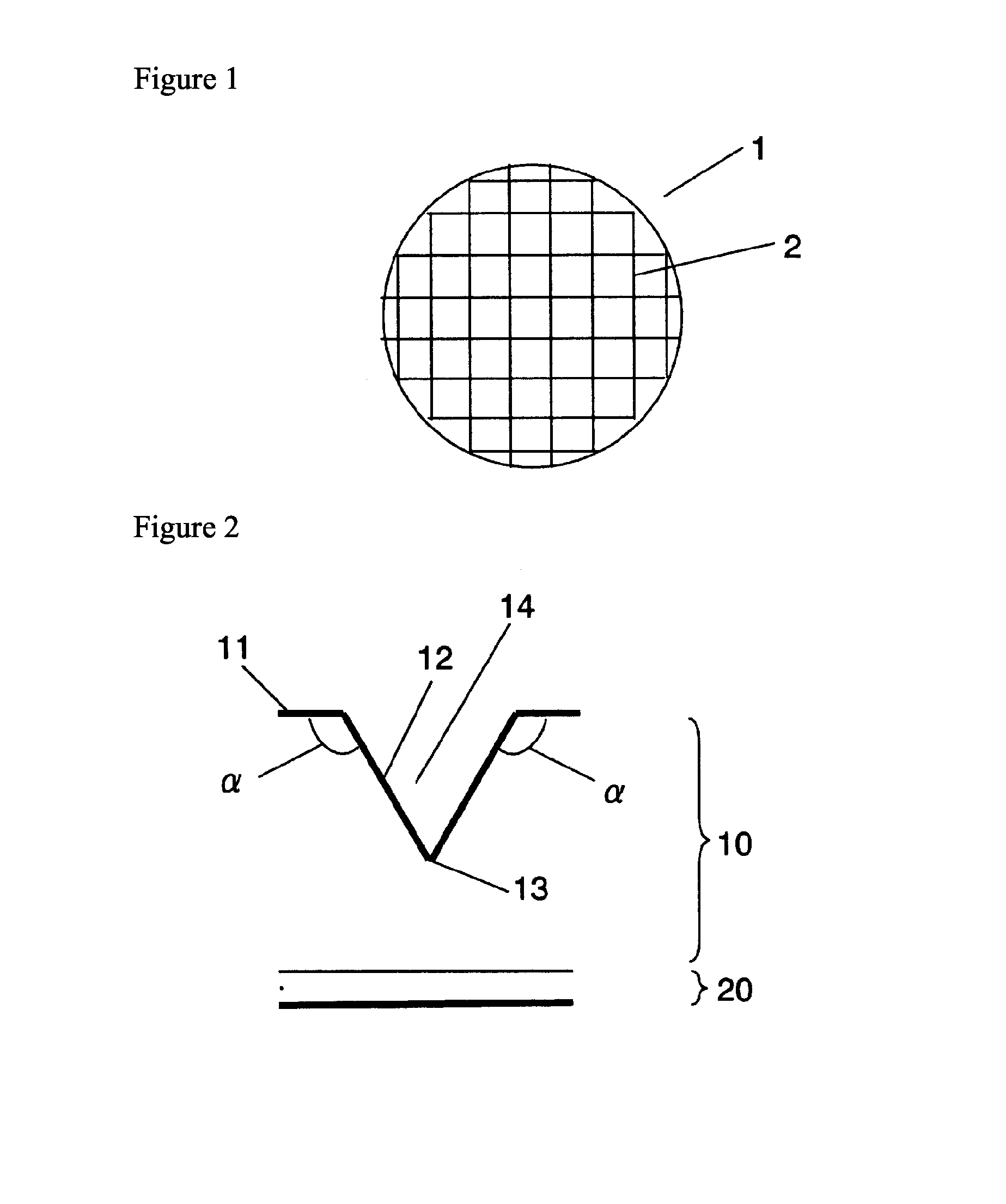
[0056]In a molding machine RIM, 30 parts by weight of polypropylene glycol, 40 parts by weight of diphenylmethane diisocyanate, 0.5 part by weight of water, 0.3 part by weight of triethylamine, 1.7 parts by weight of a silicone foam stabilizer, and 0.09 part by weight of tin octylate were mixed, and the resulting mixture was discharged to a die and molded by pressure molding to prepare a foamed polyurethane sheet including independent air bubbles.

[0057]The foamed polyurethane sheet was immersed for 60 minutes in methyl methacrylate containing 0.2 part by weight of azobisisobutyronitrile. Then, the foamed polyurethane sheet was immersed in a solution composed of 15 parts by weight of polyvinyl alcohol “CP” (polymerization degree: about 500, produced by NACALAI TESQUE, INC.), 35 parts by weight of ethyl alcohol (reagent special grade, produced by KATAYAMA CHEMICAL INDUSTRIES Co., Ltd.) and 50 parts by weight of water, and dried to coat the surface layer of the foamed polyuret...

Example

Example 2

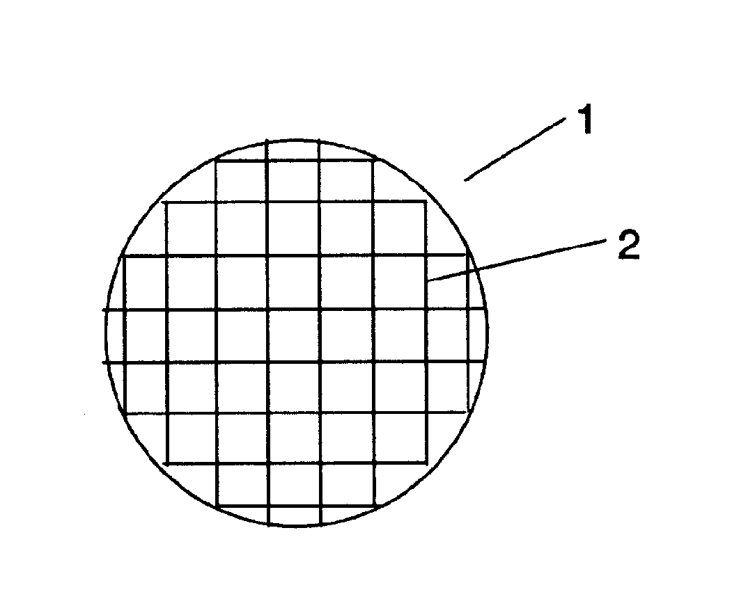
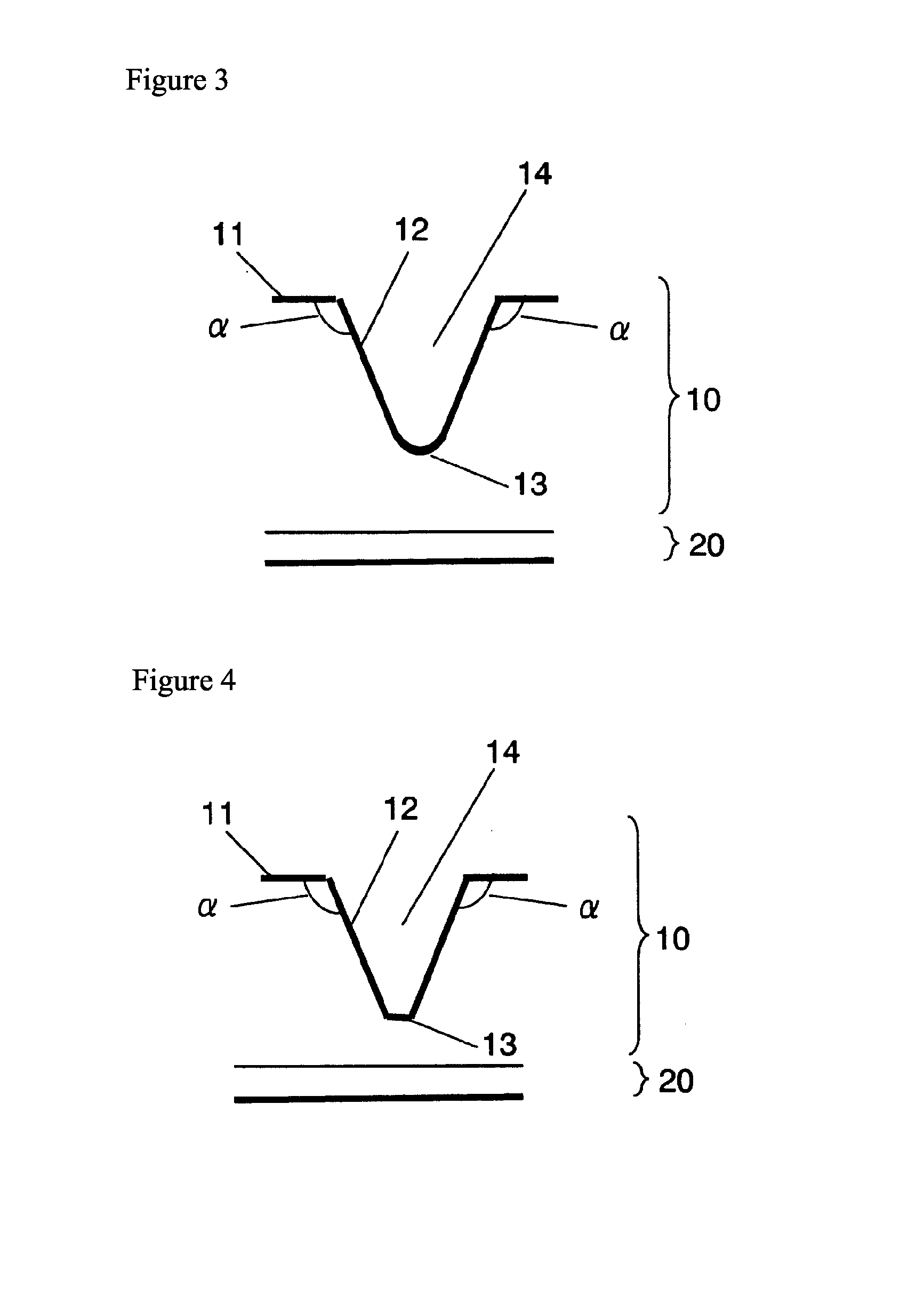
[0061]A wafer of an oxide film was polished in the same manner as in Example 1 except for changing the inclination angle of the groove on the polishing layer surface to 110°. An average polishing rate was 185.0 nm / min, and the fluctuation in a polishing rate was as good as 25.4 nm / min.

Example

Example 3

[0062]A wafer of an oxide film was polished in the same manner as in Example 1 except for changing the inclination angle of the groove on the polishing layer surface to 140°. An average polishing rate was 227.3 nm / min, and the fluctuation in a polishing rate was as good as 23.8 nm / min.


PUM


Abstract

A polishing pad comprising at least a polishing layer and a cushion layer, wherein a groove is formed on a polishing surface of the polishing pad, at least one of angles formed by the polishing surface and a side surface of the groove which continues to the polishing surface is 105-150° inclusive, and the cushion layer has a strain constant of 7.3×10⁻⁶ to 4.4×10⁻⁴ μm/Pa inclusive. The use of the polishing pad can achieve a purpose of preventing the fluctuation in a polishing rate while keeping the polishing rate at a high level.

Description

TECHNICAL FIELD[0001]The present invention relates to a polishing pad. More particularly, the present invention relates to a polishing pad which is preferably used for forming a flat surface in a semiconductor, a dielectric-metal composite and an integrated circuit.BACKGROUND ART[0002]With increases in the density of semiconductor device, technologies of multilayer wiring and the formation of an interlayer insulation film associated therewith or the formation of electrodes such as plug or damascene become more important. In association with this, the importance of a process of planarizing these interlayer insulation films and metal layers of electrodes increases, and as an efficient technology for the planarization process, a polishing technology referred to as CMP (Chemical Mechanical Polishing) has been widespread.[0003]In general, a chemical mechanical polishing apparatus is composed of a polishing head for holding a semiconductor wafer of a material to be processed, a polishing ...

Claims


Application Information

Patent Timeline
IPC IPC(8): B24B37/26
CPCB24B37/26B24B37/22
Inventor TAKEUCHI, NANAFUKUDA, SEIJIOKUDA, RYOJIKASAI, SHIGETAKA
Owner TORAY IND INC
Why Eureka
Try Eureka