
Hybrid vehicle drive system and method for fuel reduction during idle

Active Publication Date: 2014-06-19
POWER TECH HLDG LLC
View PDF1 Cites 54 Cited by
  • Summary
  • Abstract
  • Description
  • Claims
  • Application Information

AI Technical Summary

Benefits of technology

This patent describes a vehicle drive system that includes an electric motor and a control system. The electric motor can receive power from the vehicle's first prime mover and can be used to rotate the mover while the vehicle is stopped, reducing fuel consumption. The control system causes the electric motor to rotate the mover at a speed while the vehicle is stopped. This system can be easily retrofitted to existing vehicles and can be used in hybrid vehicles to improve fuel efficiency.

Problems solved by technology

One limitation of this system is that the second prime mover is typically positioned between the first prime mover and the transmission, creating the need to reposition existing drive train components.
However, series design hybrids also generally include a larger, heavier battery; have a greater demand on the engine to maintain the battery charge; and include inefficiencies due to the multiple energy conversions.
However, parallel design hybrids typically lack a no-idle system and may have non-optimal engine operation (e.g., low rpm or high transient loads) under certain circumstances.
Sophisticated power train control systems and power management systems required for the operation of a hybrid vehicle drive system can add cost and complexity.
The method also includes operating the electric motor when the vehicle is stopped to drive the first prime mover at a speed so that a control system does not provide fuel to the first prime mover during idle to reduce fuel consumption.

Method used


Image

  • Hybrid vehicle drive system and method for fuel reduction during idle
  • Hybrid vehicle drive system and method for fuel reduction during idle
  • Hybrid vehicle drive system and method for fuel reduction during idle

Examples


Embodiment Construction

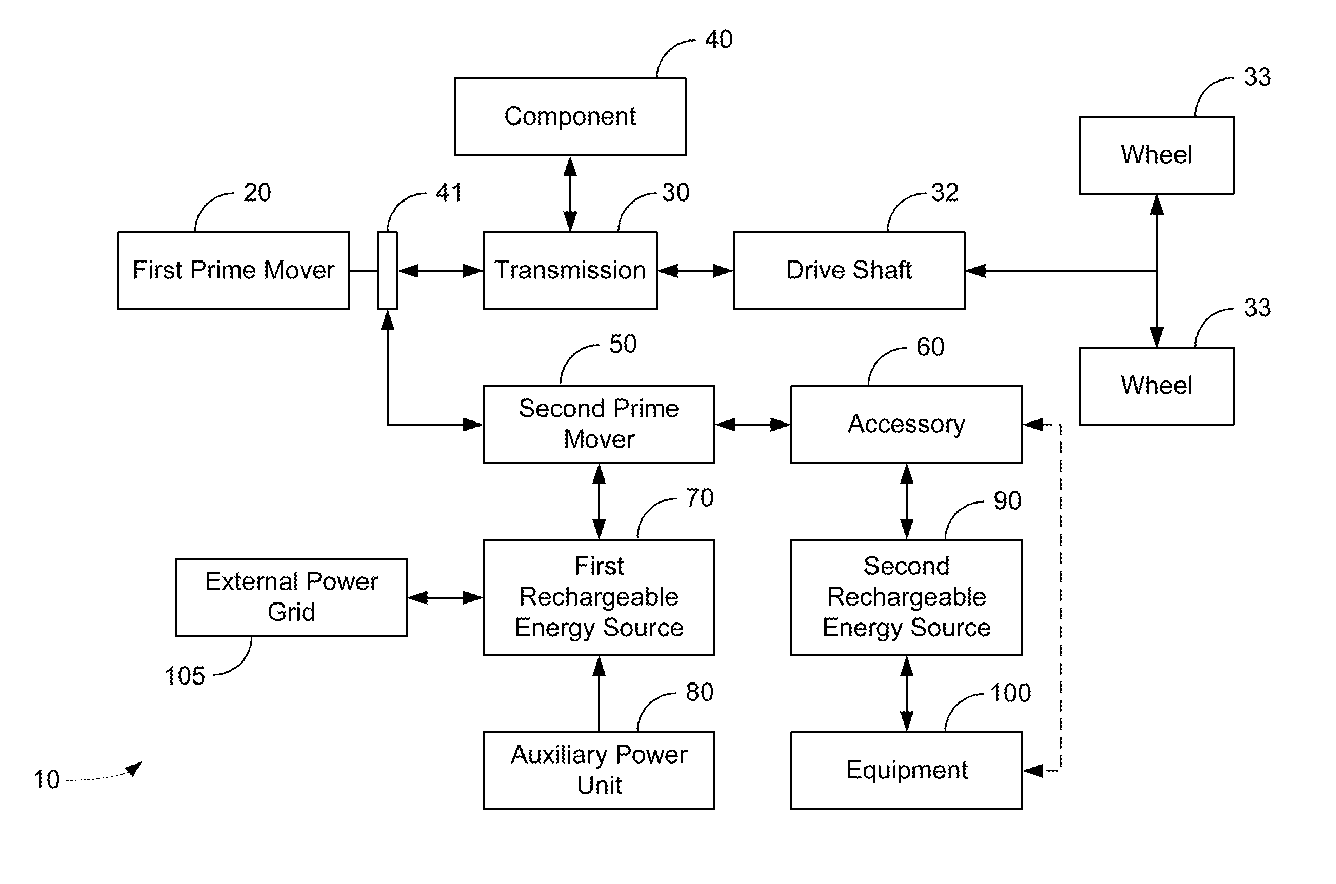
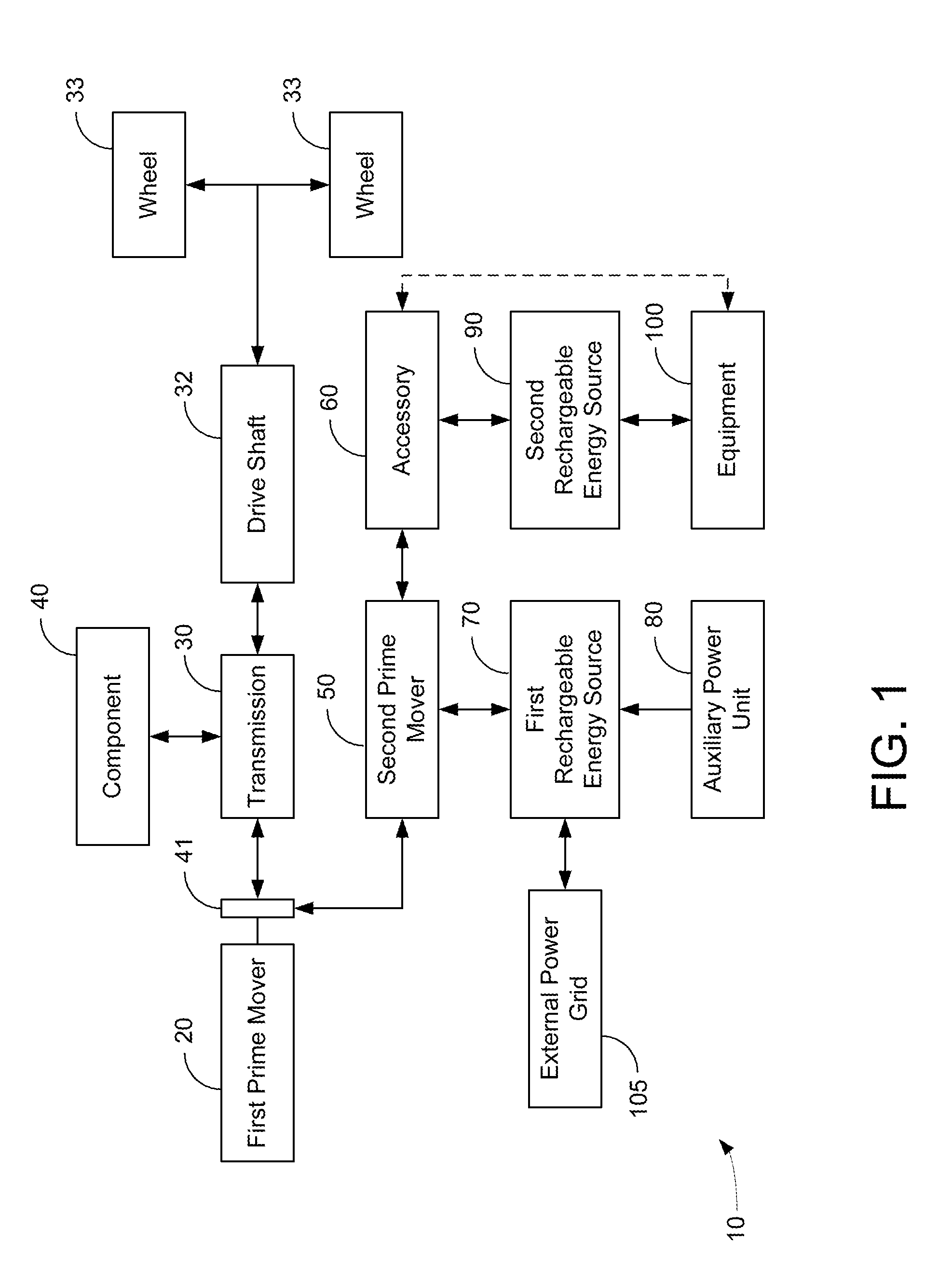
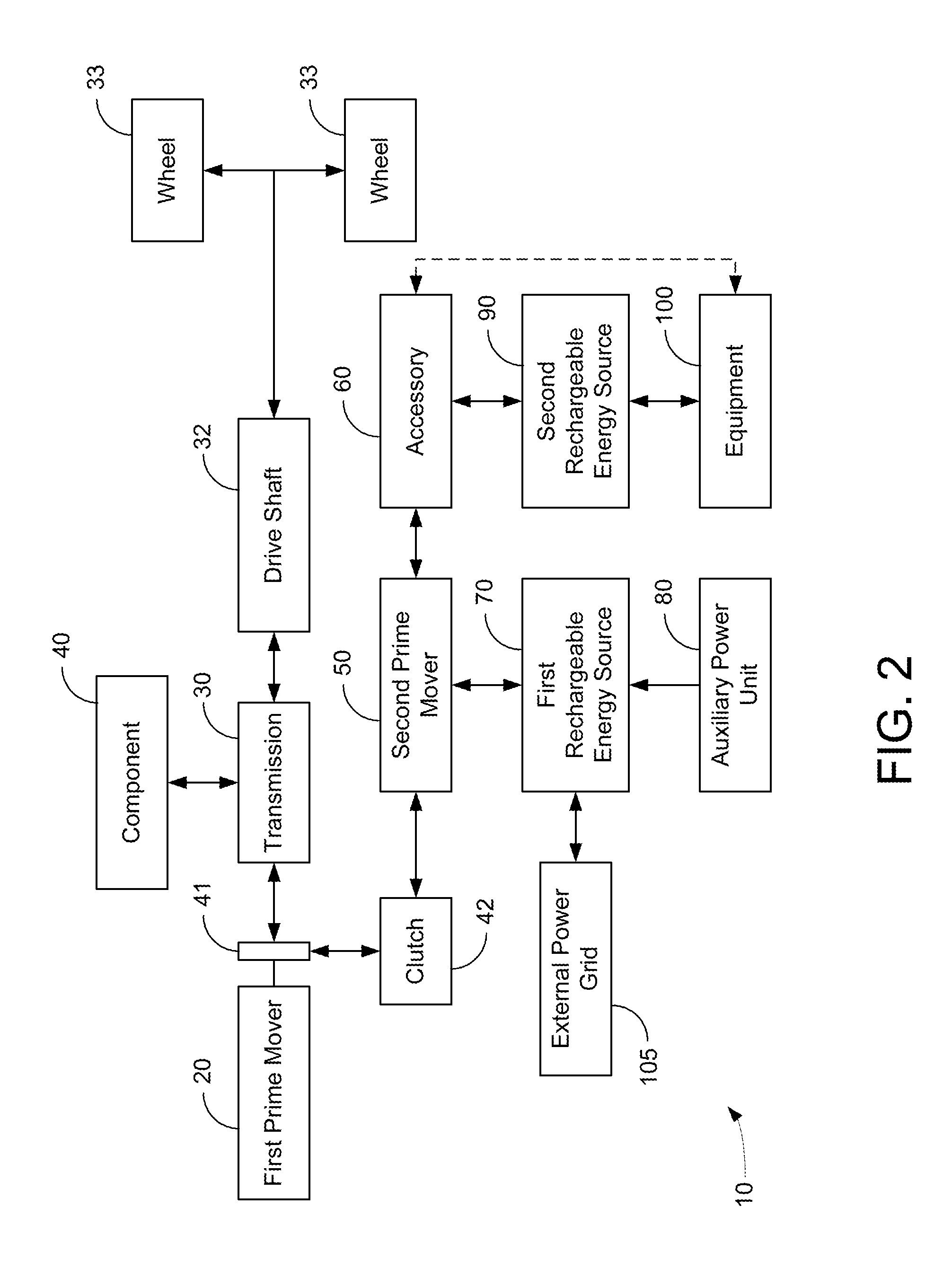
[0032]Hybrid vehicle drive systems according to several possible embodiments are presented. One feature of one exemplary embodiment of the hybrid vehicle drive system is that the hybrid drive system can utilize an interface between the first prime mover and the transmission without using a PTO. Alternatively, one exemplary embodiment of the hybrid vehicle drive system is that the hybrid drive system can utilize a PTO interface to drive electrical or hydraulic motors as discussed in the PTO hybrid architectures discussed in the applications incorporated herein by reference. Another feature of one embodiment is that a drive shaft can be powered singly or in any combination by a first prime mover, a second prime mover, and an accessory using the interface or the PTO interface. Preferred embodiments incorporate hydraulic systems into the hybrid vehicle drive system for optimal energy storage and usage. It is noted that the term motor as used herein refers to a motor / generator or motor / p...


PUM

PropertyMeasurementUnit
Poweraaaaaaaaaa
Electric chargeaaaaaaaaaa
Speedaaaaaaaaaa

Abstract

A vehicle drive system for a vehicle including a first prime mover, a first prime mover driven transmission, and a rechargeable power source can be configured for reduced fuel consumption at idle. The vehicle drive system includes an electric motor in direct or indirect mechanical communication with the first prime mover, wherein the electric motor can receive power from the first prime mover driven transmission and can receive power from the first prime mover. The vehicle drive system also includes a control system. The control system causes the electric motor to rotate the first prime mover at a speed so that an electronic control module associated with the first prime mover does not cause fuel to be provided to the first prime mover while the vehicle is stopped, thereby reducing fuel consumption at idle for the vehicle

Description

CROSS-REFERENCE TO RELATED PATENT APPLICATIONS[0001]This application is a Continuation-In-Part of US Application PCT / US2013 / 036431, filed Apr. 12, 2013 which claims priority to Provisional Application U.S. Application 61 / 624,118, filed Apr. 13, 2012, both incorporated herein by reference in their entirety, and is a Continuation-In-Part of U.S. application Ser. No. 13 / 812,723 filed Mar. 20, 2012 which claims priority to PCT Application 2012 / 029835 which claims the benefit of priority under 35 U.S.C. §119(e) to U.S. Provisional Application Ser. No. 61 / 566,526 (096637-0142), filed on Apr. 13, 2012, all incorporated herein by reference in their entireties.[0002]The application is related to application Ser. No. 13 / 629,533 filed Sep. 27, 2012, which is a divisional of U.S. Pat. No. 8,408,341 which:[0003]is a continuation-in-part of U.S. patent application Ser. No. 12 / 130,888, filed May 30, 2008, which claims the benefit of priority under 35 U.S.C. §119(e) to U.S. Provisional Application ...

Claims


Application Information

Patent Timeline
IPC IPC(8): B60W20/00
CPCY10S903/906B60W20/10B60W30/1888B60K7/0015B60K25/02B60K25/06B60K2025/005Y10T29/49716Y10S903/902B60W10/06B60W10/08B60W20/20B60W2510/18B60W2510/20B60W2510/305B60W2520/04B60W2710/08B60Y2200/92F16H61/0031Y10S903/93Y02T10/62B60W20/13B60K6/26B60K6/48B60K2006/268B60W10/30B60W20/40B60W30/1886B60W30/20B60W2030/206B60W2510/244B60W2510/30B60W2710/0644B60W2710/305
Inventor DALUM, JOSEPH T.
Owner POWER TECH HLDG LLC
Features
  • Generate Ideas
  • Intellectual Property
  • Life Sciences
  • Materials
  • Tech Scout
  • Unparalleled Data Quality
  • Higher Quality Content
  • 60% Fewer Hallucinations
Learn More