Power storage device and method for charging the same

a technology of power storage device and charging method, which is applied in the direction of secondary cell servicing/maintenance, sustainable manufacturing/processing, secondary cell details, etc., can solve the problem of reducing the capacity of the power storage device, and achieve the effect of increasing the resistance of the positive electrode and inhibiting the decrease of the battery capacity

Active Publication Date: 2014-06-26
SEMICON ENERGY LAB CO LTD
View PDF8 Cites 51 Cited by
  • Summary
  • Abstract
  • Description
  • Claims
  • Application Information

AI Technical Summary

Benefits of technology

[0018]As described above, an imbalance in the amount of inserted and extracted lithium between a positive electrode and a negative electrode can be redressed when an electrolyte solution is decomposed also at the positive electrode. For example, in the case of using lithium iron phosphate (LiFePO4) as a positive electrode active material, a redox potential of lithium iron phosphate is approximately 3.5 V, so it is sufficient that an upper limit voltage is set to 4 V. However, by intentionally raising the upper limit voltage to 4.5 V, the decomposition of the elec

Problems solved by technology

Therefore, there is an imbalance in the amount of inserted and extracted lithium between the positive el

Method used


Image

  • Power storage device and method for charging the same
  • Power storage device and method for charging the same
  • Power storage device and method for charging the same

Examples


embodiment 1

1.1. Method for Charging and Discharging Power Storage Device

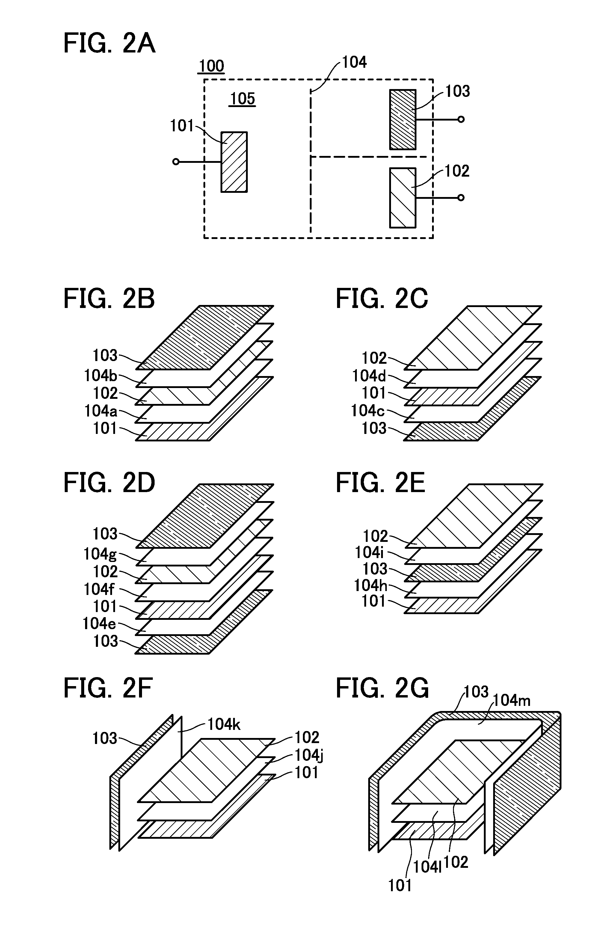
[0065]As illustrated in FIG. 2A, a power storage device 100 includes at least a negative electrode 101, a positive electrode 102, and a third electrode 103. A separator 104 is provided to prevent the negative electrode 101, the positive electrode 102, and the third electrode 103 from being short-circuited with one another. A space 105 is filled with an electrolyte solution. Each of the electrodes is described in detail later.

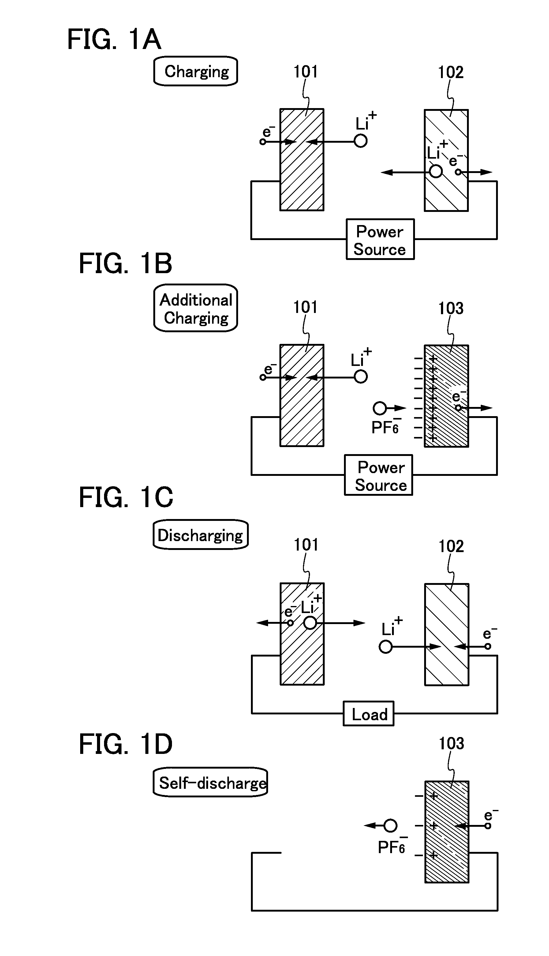
[0066]A method for charging and discharging the power storage device 100 is described with reference to FIGS. 1A to 1D. Note that the separator is not illustrated in FIGS. 1A to 1D.

[0067]As illustrated in FIG. 1A, charging of the power storage device 100 is performed by connecting the negative electrode 101 and the positive electrode 102 of the power storage device 100 to a power source such as a system power supply. When the power storage device 100 is a lithium-ion secondary battery, a carrier ion (a...

embodiment 2

2. Control Circuit

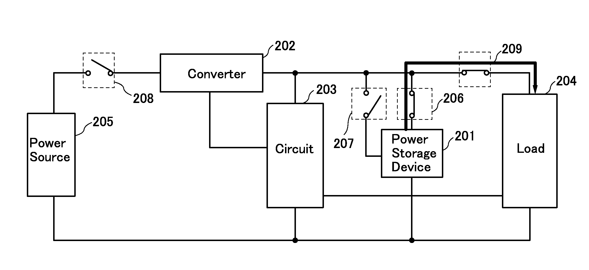
[0110]An example of the circuit 203 is described with reference to FIG. 6.

2.1. Circuit Configuration

[0111]The circuit 203 includes a processor 710, a bus bridge 711, a memory 712, a memory interface 713, a controller 720, an interrupt controller 721, an I / O interface (input-output interface) 722, and a power gate unit 730.

[0112]The circuit 203 further includes a crystal oscillation circuit 741, a timer circuit 745, an I / O interface 746, an I / O port 750, a comparator 751, an I / O interface 752, a bus line 761, a bus line 762, a bus line 763, and a data bus line 764. Furthermore, the circuit 203 includes at least connection terminals 770 to 776 as portions for connection to an external device. Note that each of the connection terminals 770 to 776 represents one terminal or a terminal group including a plurality of terminals. An oscillation unit 742 including a quartz crystal unit 743 is connected to the circuit 203 through the connection terminal 772 and the connectio...

embodiment 3

3. Power Storage Device

[0147]As an example of a power storage device, a nonaqueous secondary battery typified by a lithium-ion secondary battery is described.

3.1. Positive Electrode

[0148]First, a positive electrode of the power storage device is described with reference to FIGS. 7A and 7B.

[0149]A positive electrode 6000 includes a positive electrode current collector 6001 and a positive electrode active material layer 6002 formed over the positive electrode current collector 6001 by a coating method, a CVD method, a sputtering method, or the like, for example. Although an example of providing the positive electrode active material layer 6002 on both surfaces of the positive electrode current collector 6001 with a sheet shape (or a strip-like shape) is illustrated in FIG. 7A, one embodiment of the present invention is not limited to this example. The positive electrode active material layer 6002 may be provided on one of the surfaces of the positive electrode current collector 6001. ...


PUM


Abstract

A decrease in the capacity of a power storage device is inhibited by adjusting or reducing imbalance in the amount of inserted and extracted carrier ions between positive and negative electrodes, which is caused by decomposition of an electrolyte solution of the negative electrode. Further, the capacity of the power storage device can be restored. Furthermore, impurities in the electrolyte solution can be decomposed with the use of the third electrode. A power storage device including positive and negative electrodes, an electrolyte, and a third electrode is provided. The third electrode has an adequate electrostatic capacitance. The third electrode can include a material with a large surface area. In addition, a method for charging the power storage device including the steps of performing charging by applying a current between the positive and negative electrodes, and performing additional applying a current between the third electrode and the negative electrode is provided.

Description

BACKGROUND OF THE INVENTION[0001]1. Field of the Invention[0002]The present invention relates to an object (a product including a machine, a manufacture, and a composition of matter) and a method (a process including a simple method and a production method). In particular, one embodiment of the present invention relates to a power storage device, a power storage system, a semiconductor device, a display device, a light-emitting device, another electrical device, a manufacturing method thereof, or a driving method thereof. In particular, one embodiment of the present invention relates to a power storage device and a method for charging the power storage device.[0003]2. Description of the Related Art[0004]A variety of power storage devices, for example, non-aqueous secondary batteries such as lithium-ion secondary batteries, lithium-ion capacitors, and air cells have been actively developed in recent years. In particular, demand for lithium-ion secondary batteries with high output and...

Claims


Application Information

Patent Timeline
IPC IPC(8): H02J7/00H01M10/46H01M10/42
CPCH02J7/0052H01M10/425H01M10/46H02J7/35H01M10/02H01M10/045H01M10/0525H01M10/0583H01M10/0585H01M4/96H01M10/4242H01M10/44H01M2004/025H02J7/007Y02E60/10Y02E60/50H01M50/46Y02P70/50H02J50/12H01M10/058H01M10/446H01M10/4235H01M4/625H01M10/052H02J7/0069H02J50/80H02J50/20Y02T10/70H01M2010/4271H02J7/0068
Inventor MOMO, JUNPEIMIYAKE, HIROYUKITAKAHASHI, KEI
Owner SEMICON ENERGY LAB CO LTD
Why Eureka
Try Eureka