Antenna system

a technology of anantenna and a lens, applied in the field of anantenna systems, can solve the problems of not being adapted to a situation, prior art solutions with spherical shapes are not adapted, etc., and achieve the effect of good focusing

Active Publication Date: 2014-06-26
CANON KK
View PDF2 Cites 23 Cited by
  • Summary
  • Abstract
  • Description
  • Claims
  • Application Information

AI Technical Summary

Benefits of technology

[0019]Preferably, the dielectric member cross section has a rectangular shape. The rectangular cross section allows internal reflection and recombination of the electromagnetic waves. Thus, a good focusing effect can be obtained in the elevation plane, while keeping rather small dimensions.
[0020]According to the embodiment proposed here, the dielectric member has a height, in a direction parallel to the axis of the cylindrical lens, larger than a thickness of the cylindrical lens in said direction. Thus, despite the rather broad radiation patte...

Problems solved by technology

These prior art solutions with spherical shapes are however not adapted to cases where the angle of radiation in elevation and the capability of beam steering in azimut...

Method used


Image

  • Antenna system
  • Antenna system
  • Antenna system

Examples


Embodiment Construction

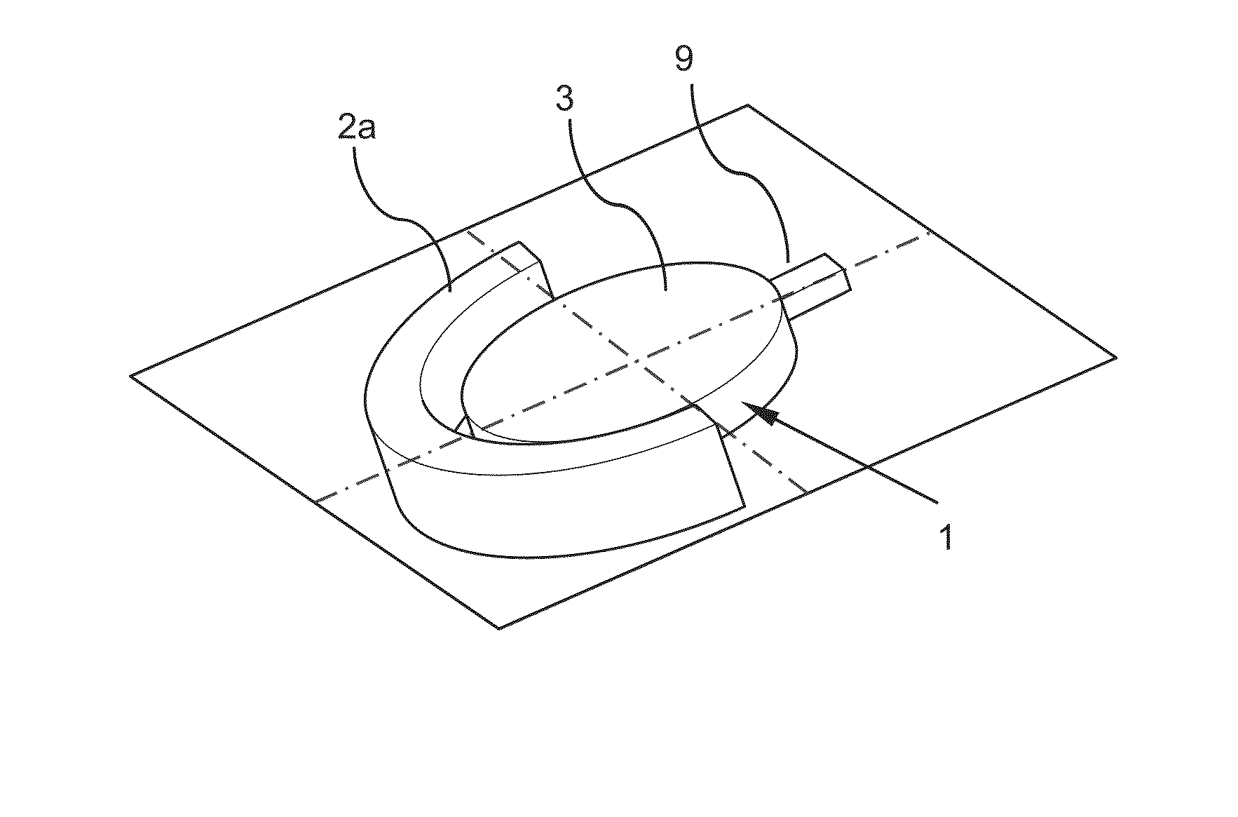
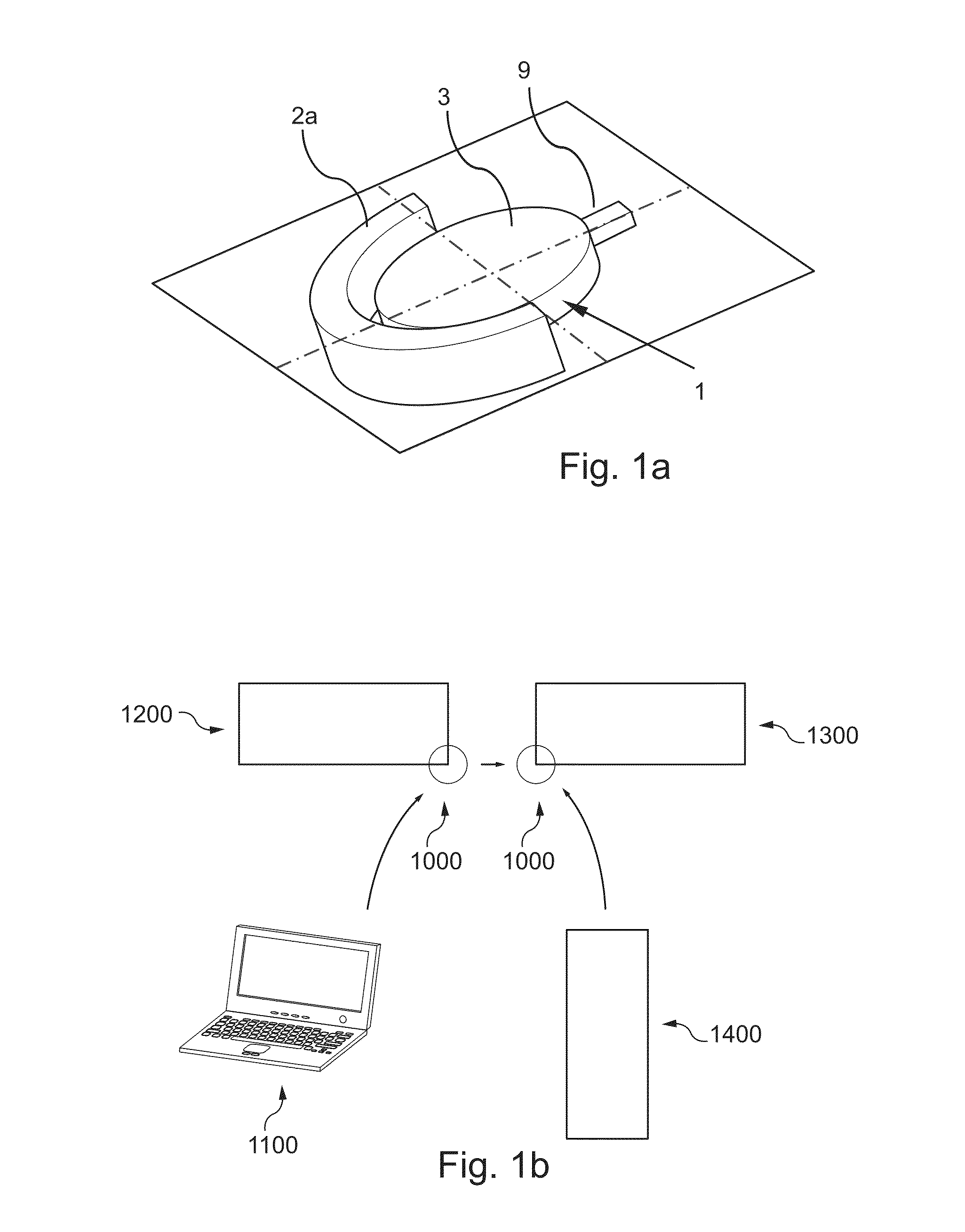
[0100]FIG. 1a shows an antenna system, here used as a radiating device, designed according to the teachings of the invention.

[0101]This antenna system includes a cylindrical electromagnetic lens 1 and a superstrate 2a coupled to the cylindrical lens 1.

[0102]As it will be explained in further detail below, this cylindrical lens 1 is composed of several crows 6, 7, 8, as visible in FIG. 3a, in order to be in conformity with the Lüneburg law. This cylindrical lens is for instance implemented in the form of the electromagnetic lens 200 presented below with reference to FIG. 5a in particular.

[0103]In the embodiment shown in FIG. 1a, the cylindrical lens 1 is sandwiched between a top shield 3 and a bottom shield 4 made of a conductive material, the top shield 3 and the bottom shield thus forming a conductive mounting receiving the cylindrical lens 1.

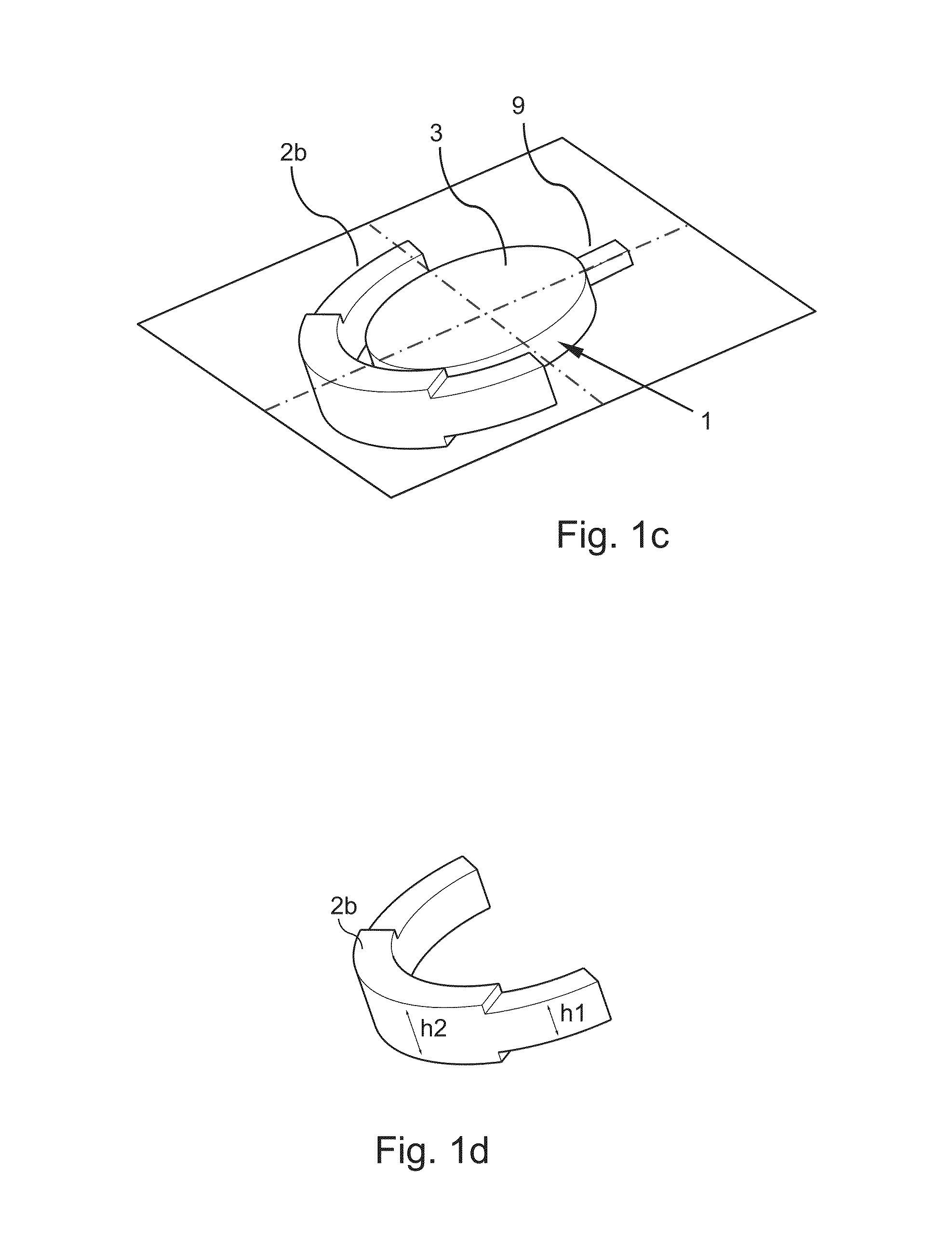
[0104]The superstrate 2a is a ring-shaped member made of a dielectric material (e.g. Teflon®, i.e. PTFE: polytetrafluoroethylene) and partial...


PUM


Abstract

An antenna system having a cylindrical electromagnetic lens configured to guide at least one electromagnetic signal to an emerging area by means of at least a variation in dielectric permittivity, thereby generating a beam output from the emerging area. The antenna system has a dielectric member configured to receive the beam output from the emerging area and to focus the beam in an elevation plane perpendicular to a planar face of the cylindrical electromagnetic lens. The cylindrical electromagnetic lens is received in a conductive mounting, and the mounting carries the dielectric member.

Description

[0001]This application claims the benefit of Great Britain Patent Application No. 1223096.7 filed Dec. 20, 2012 and Great Britain Patent Application No. 1317616.9 filed Oct. 4, 2013, which are hereby incorporated by reference herein in their entireties.FIELD OF THE INVENTION[0002]The invention relates to antenna systems, more specifically millimetre wave devices aiming at providing indoor or outdoor wireless transmission.BACKGROUND OF THE INVENTION[0003]The principle of spherical electromagnetic lenses having a gradient of decreasing refractive index was introduced in 1964 by Rudolf Luneburg in Mathematical Theory of Optics, Cambridge University Press. The dielectric constant of the lens, now known as Luneburg lens, is such that ∈r=2−(r / R)2,[0004]where ∈r is the relative dielectric constant, r the position considered along the radius, and R is the radius of the lens. Obviously in this case, the dielectric permittivity shall vary from 1 to 2.[0005]With such a lens an incoming front w...

Claims


Application Information

Patent Timeline
IPC IPC(8): H01Q15/08
CPCH01Q15/08H01Q15/10H01Q19/06H01Q19/062H01Q21/0031
Inventor MERLET, HERVEVISA, PIERRELAFOND, OLIVIERHIMDI, MOHAMMEDBOR, JONATHAN
Owner CANON KK
Why Eureka
Try Eureka