Overcurrent protection device, overcurrent protection method, and non-transitory medium

a protection device and overcurrent protection technology, applied in the direction of electric devices, hybrid vehicles, propulsion by batteries/cells, etc., can solve the problems of sputtering of the fuse, failure to cause,

Active Publication Date: 2014-06-26
TOYOTA JIDOSHA KK
View PDF1 Cites 9 Cited by
  • Summary
  • Abstract
  • Description
  • Claims
  • Application Information

AI Technical Summary

Benefits of technology

[0007]The invention provides an overcurrent protection device, an overcurrent protection method, and a non-transitory medium that can adequately protect a circuit, without causing a failure induced by a blown fuse.
[0013]In accordance with the aspects of the invention, the fuse element is heated by heat generated by application of power to the component of the auxiliary circuit, or to the power supply component of the power supply circuit, and the energizing current that is required to flow in the fuse element in order to melt the fuse element can be reduced. Therefore, the circuit positioned on the grounding side with respect to the fuse element in the main circuit can be adequately protected.

Problems solved by technology

Therefore, a failure can be caused by the sputtering of the blown fuse.

Method used


Image

  • Overcurrent protection device, overcurrent protection method, and non-transitory medium
  • Overcurrent protection device, overcurrent protection method, and non-transitory medium
  • Overcurrent protection device, overcurrent protection method, and non-transitory medium

Examples


Embodiment Construction

[0022]The embodiments of the invention are described hereinbelow with reference to the appended drawings.

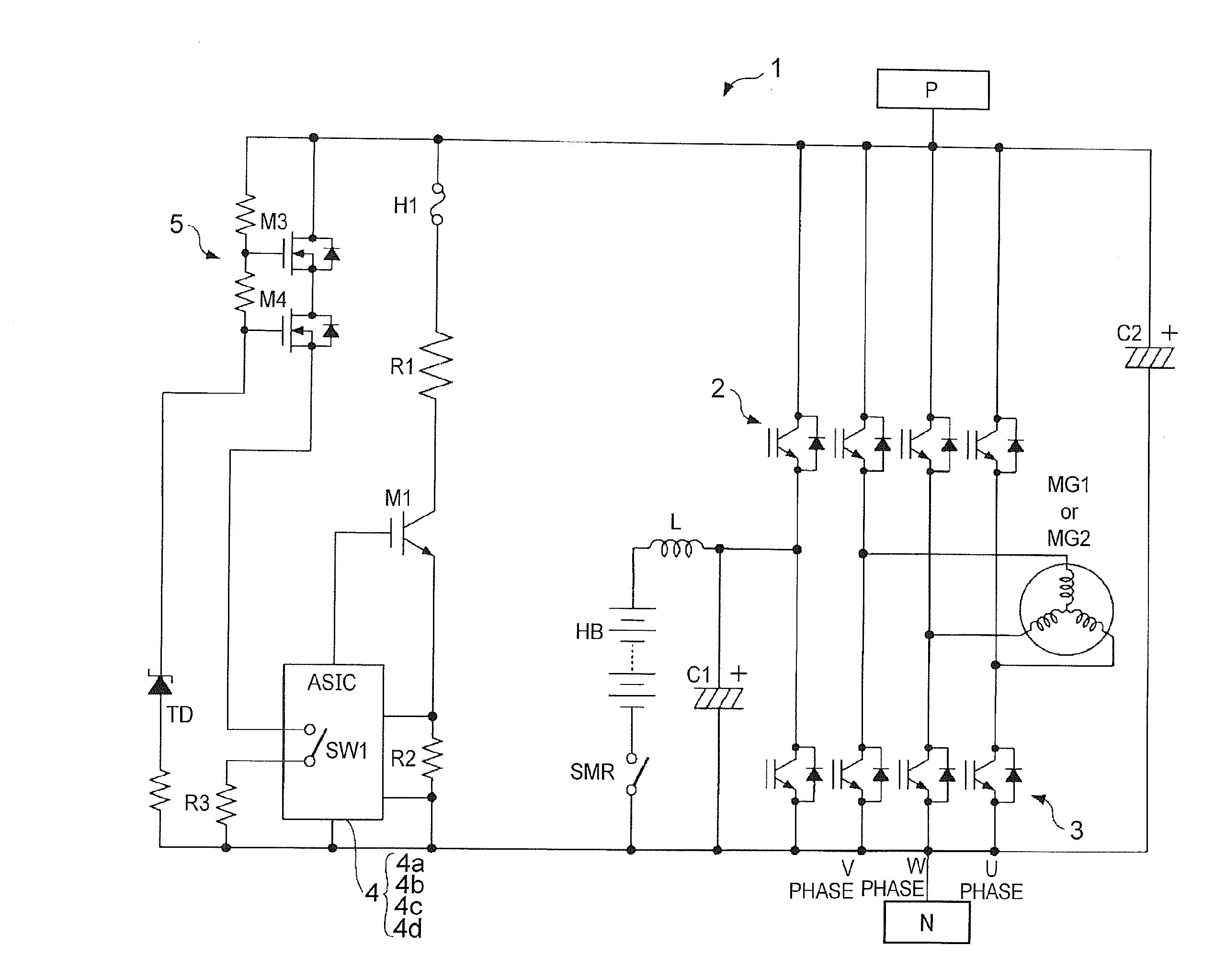
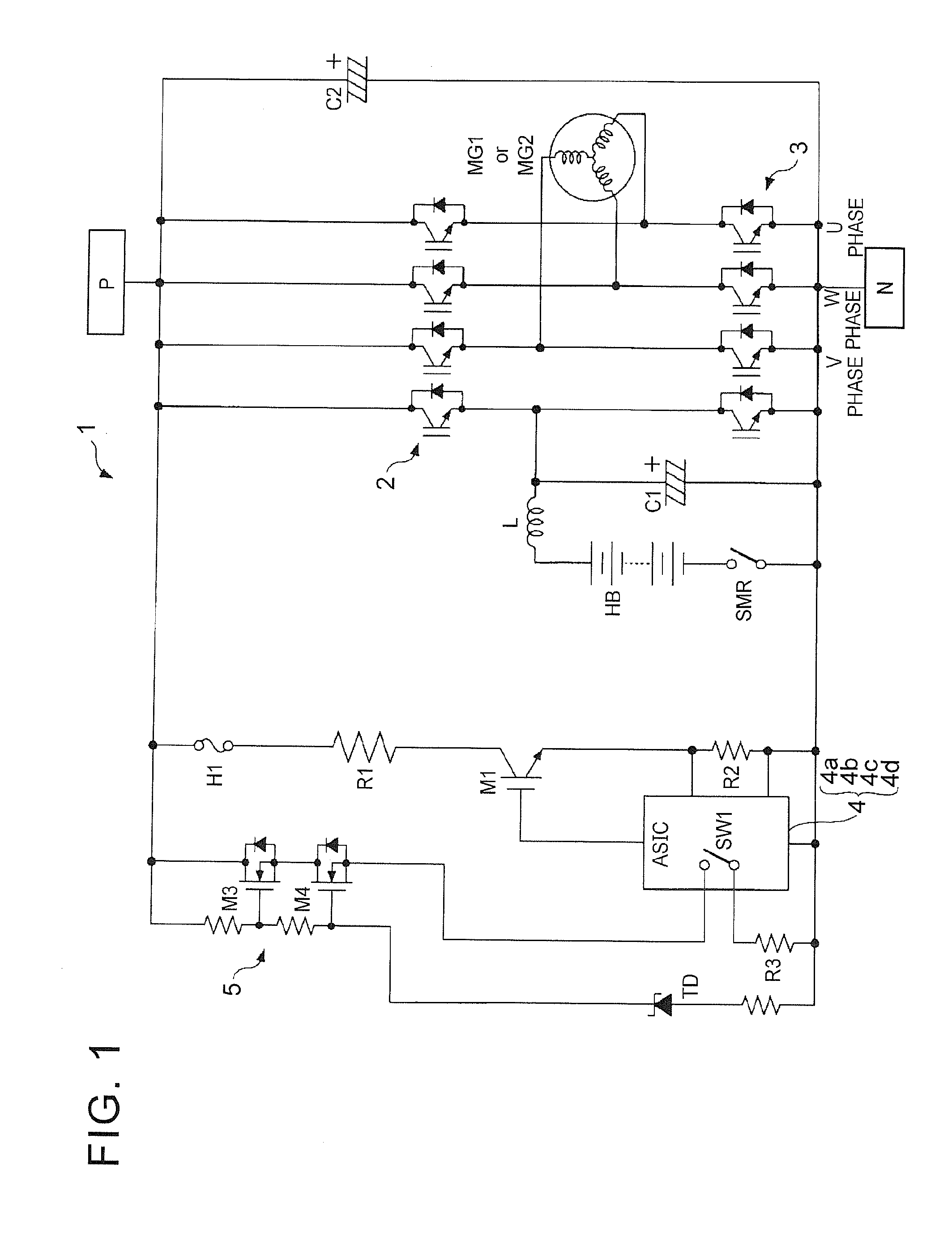
[0023]As shown in FIG. 1, an overcurrent protection device 1 of the present example includes a converter 2, a discharge IGBTM1 (discharge unit), a discharge resistor R1, a detection unit 4a, and a control unit 4b. The converter 2 constitutes a main circuit. The discharge IGBTM1 discharges electric charges of a high-voltage unit P of the inverter 3. The detection unit 4a detects the leak current (energizing current) of the discharge IGBTM1 with a discharge detection resistor R2. The control unit 4b controls ON / OFF switching of the discharge IGBTM1.

[0024]The overcurrent protection device 1 also includes power supply components M3, M4 (components), a power supply circuit 5 (auxiliary circuit), and a fuse H1 (fuse element). The power supply components M3, M4 (components) supply electric power to the control unit 4b on the basis of power from the high-voltage unit P. The control unit ...


PUM


Abstract

An overcurrent protection device includes a fuse element and an auxiliary circuit. Power is applied from a high-voltage unit of a main circuit to the fuse element. The auxiliary circuit includes a component which heats the fuse element. An amount of electric current flowing in the fuse element when the fuse element melts is controlled by heat generated by the component.

Description

INCORPORATION BY REFERENCE[0001]The disclosure of Japanese Patent Application No. 2012-281555 filed on Dec. 25, 2012 including the specification, drawings and abstract is incorporated herein by reference in its entirety.BACKGROUND OF THE INVENTION[0002]1. Field of the Invention[0003]The invention relates to an overcurrent protection device, an overcurrent protection method, and a non-transitory medium for preventing, by fuse blowing, the occurrence of component or circuit failure caused by overcurrent.[0004]2. Description of Related Art[0005]A technique using a fuse for protecting a circuit including a passive component such as an insulated gate bipolar transistor (IGBT), a metal-oxide-semiconductor field-effect transistor (MOSFET), and a resistor is disclosed, for example, in the below-described Japanese Patent Application Publication No. 2004-153944 (JP 2004-153944 A).[0006]In such a device, a separate semiconductor device is provided for grounding the fuse, and the fuse is itself...

Claims


Application Information

Patent Timeline
Patent Type & Authority Applications(United States)
IPC IPC(8): H02H5/04B60L50/15H02M1/00
CPCH02H3/085B60L3/0069B60L7/16B60L50/61H02H3/046Y02T10/62Y02T10/70Y02T10/7072
Inventor UEDA, KAZUHIKO
Owner TOYOTA JIDOSHA KK
Why Eureka
Try Eureka