Turbine blade

a turbine blade and blade technology, applied in the field of turbine blades, can solve the problems of conflicting performance characteristics between aerodynamics and heat transfer, current squealer designs are mostly unable to explore the full aerodynamic potential of the squealer working mechanism, etc., to achieve good aerodynamic performance, improve the cooling of the blade tip, and increase the space for cooling chambers

Inactive Publication Date: 2014-06-26
ROLLS ROYCE PLC
View PDF6 Cites 54 Cited by
  • Summary
  • Abstract
  • Description
  • Claims
  • Application Information

AI Technical Summary

Benefits of technology

[0012]The sloping side provides more flexibility for the positioning of cooling chambers within the blade so as to achieve improved cooling of the blade tip.
[0013]An angle in the range of 20° to 70° is selected because this provides a balance between providing an increased space for cooling chambers within the blade tip and the need to ensure good aerodynamic performance. It has been found that with this angle range open type flow separation occurs over the rib, leading to a large vortical flow structure in the tip cavity, the above selected angle ensuring that there is a sufficiently large cavity volume to ensure such a vortical flow structure.
[0014]Aerodynamic performance has been found to be improved with a smaller width Wps. However, a problem with squealer tips of the pr

Problems solved by technology

As a result, current squealer designs are mostly unable to explore the full aerodynamic potential of the squealer working mechanism due to the restrictions arisen from the enhan

Method used


Image

  • Turbine blade
  • Turbine blade
  • Turbine blade

Examples


Embodiment Construction

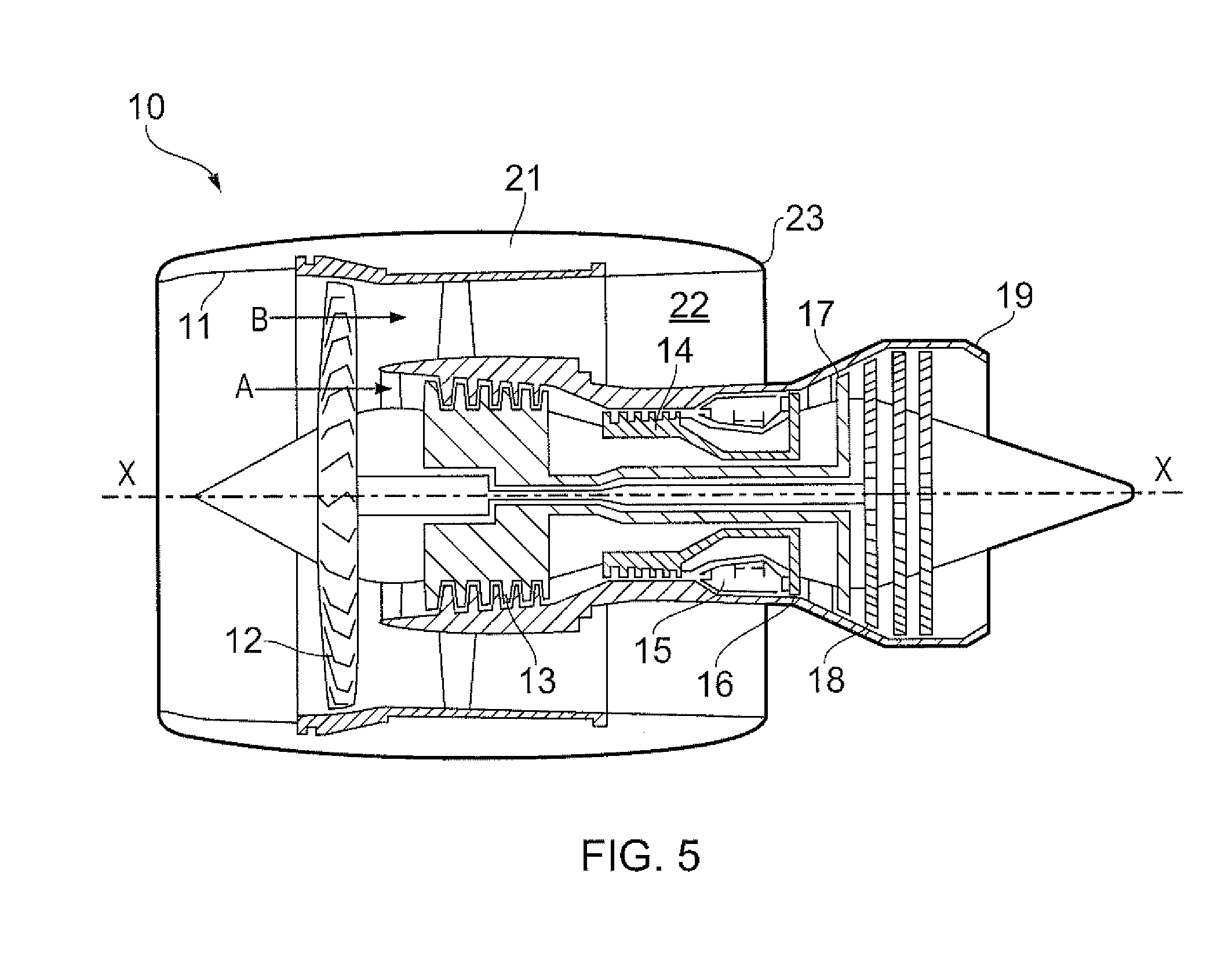
[0050]With reference to FIG. 5, a ducted fan gas turbine engine generally indicated at 10 has a principal and rotational axis X-X. The engine comprises, in axial flow series, an air intake 11, a propulsive fan 12, an intermediate pressure compressor 13, a high-pressure compressor 14, combustion equipment 15, a high-pressure turbine 16, and intermediate pressure turbine 17, a low-pressure turbine 18 and a core engine exhaust nozzle 19. A nacelle 21 generally surrounds the engine 10 and defines the intake 11, a bypass duct 22 and a bypass exhaust nozzle 23.

[0051]The gas turbine engine 10 works in a conventional manner so that air entering the intake 11 is accelerated by the fan 12 to produce two air flows: a first air flow A into the intermediate pressure compressor 13 and a second air flow B which passes through the bypass duct 22 to provide propulsive thrust. The intermediate pressure compressor 13 compresses the air flow A directed into it before delivering that air to the high pre...


PUM


Abstract

A rotor stage of a turbine has a rotational axis, a shroud and radially inward thereof a turbine blade defined partly by a pressure side wall, a suction side wall and a tip portion. The tip portion has a pressure side tip rib and a tip cavity floor defining a tip cavity. The pressure side tip rib has a width Wps, a height Hps above the tip cavity and defines a tip gap Gps with the shroud. The pressure side tip rib has a sloping side joining the tip cavity floor and having an angle αps to a radial line ZZ. The width Wps is in the range Gps to 5Gps, the height Hps is in the range 5Gps to 15Gps and the angle αps is in the range 20° to 70°.

Description

TECHNICAL FIELD[0001]The present invention relates to an aerofoil structure, typically of a turbine blade for a gas turbine engine, and in particular a structure of the tip of the aerofoil.BACKGROUND[0002]For turbine rotor blades and particularly high pressure (HP) turbine blades, there is an industry wide and an ever-important object to minimise over-tip leakage of hot working gases between a tip of the blades and a casing. In general, there are three types of tip geometry configurations which attempt to minimise over tip leakage: un-shrouded, partially shrouded and fully shrouded.[0003]As shown in FIG. 1, the simplest un-shrouded rotor blade tip 112 of a rotor blade 110 is a flat-tip arrangement having a generally planar radially outward facing surface. However, this flat-tip design is typically associated with considerable aerodynamic and heat losses due to the over-tip leakage flow of the main working gas. To reduce over-tip leakage, other blade tip configurations have been prop...

Claims


Application Information

Patent Timeline
IPC IPC(8): F01D5/18F01D11/08
CPCF01D5/20F05D2250/13F01D5/187F01D11/08
Inventor HE, LIZHANG, QIANGRAWLINSON, ANTHONY JOHN
Owner ROLLS ROYCE PLC
Why Eureka
Try Eureka