
Parabolic antenna with an integrated sub reflector

a technology of parabolic antenna and sub reflector, which is applied in the field of sensors, can solve the problems of affecting the stability of the antenna, disrupting the electromagnetic radiation field, and reducing the signal-to-noise ratio, and achieves the effect of increasing mechanical stability and high stability

Active Publication Date: 2014-07-03
VEGA GRIESHABER GMBH & CO
View PDF10 Cites 14 Cited by
  • Summary
  • Abstract
  • Description
  • Claims
  • Application Information

AI Technical Summary

Benefits of technology

The present invention provides a sensor for a fill level measuring device that uses high-frequency signals to determine the level of liquid in a container. The sensor includes a main reflector, a sub reflector, an inner space, and a hollow waveguide. The radome, which is the outer part of the sensor, is connected to the sub reflector and is made of a dielectric material with a reflective coating. The sensor is designed to have a large active antenna surface and increased efficiency of radiated power. The sensor is also sealed to prevent corrosive vapors from damaging it. The main reflector and sub reflector can be produced together in a modular structure, and the sensor can be made of a metal or plastic material. The thickness of the radome is designed to minimize interfering reflections. The technical effects of the invention include improved mechanical stability, increased efficiency of radiated power, and reduced interfering reflections.

Problems solved by technology

However, part of the electromagnetic wave exiting the waveguide is reflected and deflected by this retention clip, so that the emitted electromagnetic radiation field is disrupted.
However, during measurement, such undesirable reflections lead to an objectionable reduction in the signal-to-noise ratio, which can in some cases be substantial, and which can cause the echo to disappear into noise, making measurement of the fill level impossible.
However, this device has the disadvantage that, on one hand, only part of the electromagnetic radiation is available for measuring the fill level, and on the other hand, by mounting the exciter with the hollow waveguide, additional interference with the electromagnetic field can occur.

Method used


Image

  • Parabolic antenna with an integrated sub reflector
  • Parabolic antenna with an integrated sub reflector
  • Parabolic antenna with an integrated sub reflector

Examples


Embodiment Construction

[0031]Reference will now be made in detail to embodiments of the invention. Wherever possible, same or similar reference numerals are used in the drawings and the description to refer to the same or like parts or steps. The drawings are in simplified form and are not to precise scale. The word ‘couple’ and similar terms do not necessarily denote direct and immediate connections, but also include connections through intermediate elements or devices. For purposes of convenience and clarity only, directional (up / down, etc.) or motional (forward / back, etc.) terms may be used with respect to the drawings. These and similar directional terms should not be construed to limit the scope in any manner. It will also be understood that other embodiments may be utilized without departing from the scope of the present invention, and that the detailed description is not to be taken in a limiting sense, and that elements may be differently positioned, or otherwise noted as in the appended claims wi...


PUM


Abstract

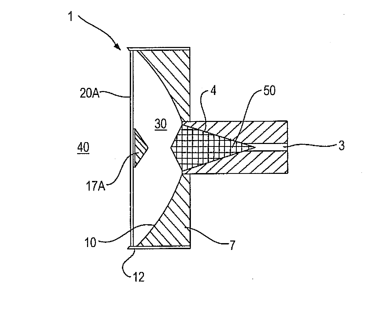
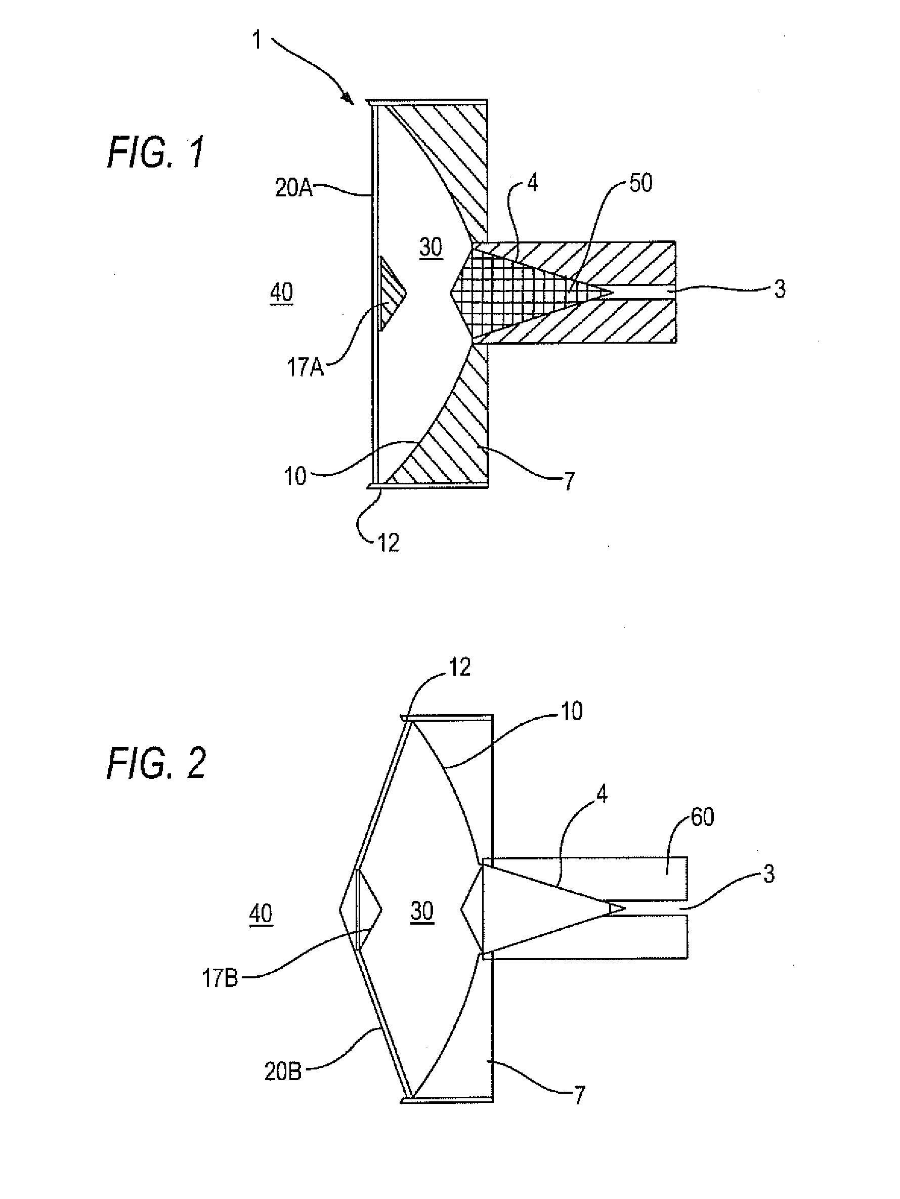
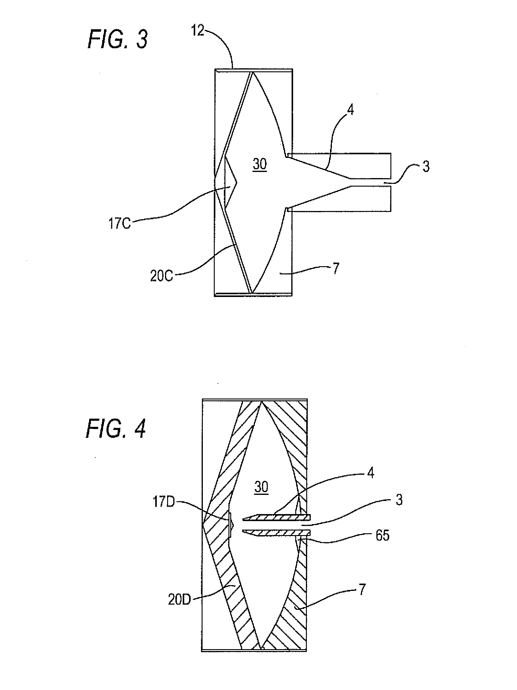
A sensor for a fill level measuring device for determining the fill level in a container by determining the delay time of high-frequency signals, comprising a main reflector having an edge region and an inner region, a sub reflector, which is connected to the edge region of the main reflector via a radome, an inner space, which is encompassed by the radome and the main reflector, and a hollow waveguide which is connected to the main reflector and has a front end, which is oriented toward the sub reflector for coupling electromagnetic waves in and / or out, wherein the radome and the sub reflector are embodied as integral or unitary in formation.

Description

CROSS REFERENCE TO RELATED APPLICATION[0001]This application claims priority from, and relates to European Ser. No. 13 150 192.6 filed Jan. 3, 2013, the entire contents of which are incorporated herein fully by reference.FIGURE FOR PUBLICATION[0002]FIG. 1BACKGROUND OF THE INVENTION[0003]1. Field of the Invention[0004]The present invention relates to a sensor for measuring the fill level in a container. More particularly, the present invention provides a parabolic antenna with a sub reflector integrated into the radome.[0005]2. Description of the Related Art[0006]Sensors designed for measuring the fill level in a container that is filled with a liquid or with bulk material by determining the delay time of high-frequency signals are known in the art, wherein the sensor is embodied as a parabolic antenna which comprises a main reflector, a sub reflector, and a hollow waveguide, which is connected to the main reflector and which is oriented with its front end toward the sub reflector fo...

Claims


Application Information

Patent Timeline
Patent Type & Authority Applications(United States)
IPC IPC(8): G01F23/284
CPCG01F23/284H01Q1/225H01Q1/42H01Q19/19
Inventor KIENZLE, KLAUS
Owner VEGA GRIESHABER GMBH & CO
Learn More