Laminated core assembly

a technology of laminated core and electric generator, which is applied in the direction of electric generator control, machine/engine, and magnetic circuit shape/form/construction, etc. it can solve the problems of increasing the thermal stress of the windings, damage to the laminated pole shoe core, and the above mentioned solutions have a very low cooling performance or are time and cost extensive, so as to improve the heat release of the laminated core assembly

Inactive Publication Date: 2014-07-03
WOBBEN PROPERTIES GMBH
View PDF9 Cites 13 Cited by
  • Summary
  • Abstract
  • Description
  • Claims
  • Application Information

AI Technical Summary

Benefits of technology

[0007]One or more embodiments of the present invention are directed to solving, or at least to reducing, at least one of the above-described problems

Problems solved by technology

This increases the thermal stress on the windings and insulations arranged on the individual laminated pole shoe cores and, as a consequence, may lead to damage at the laminated pole shoe core due to overheating.
Some of these above mentioned solutions have a very low cooling performance or ar

Method used


Image

  • Laminated core assembly
  • Laminated core assembly
  • Laminated core assembly

Examples


Embodiment Construction

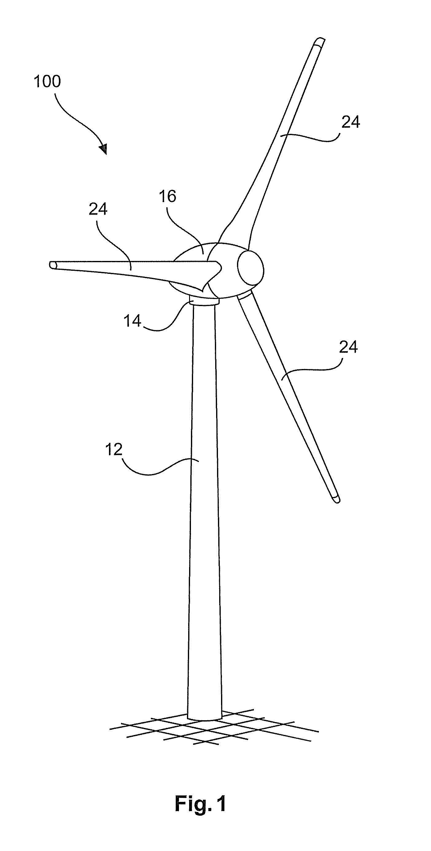
[0045]FIG. 1 shows a highly simplified illustration of a wind turbine, which in its entirety is marked with reference number 100. The tower has reference number 12, the nacelle 16 (alternatively, instead of the term nacelle, the term machine housing may be used as well). The nacelle 16 is mounted to the head of the tower by means of a azimuth bearing (not shown) in such a way that wind direction tracking can be realized through azimuth drives (also not shown). The transition between the nacelle 16 and the tower 12 is covered by a nacelle apron 14 and thus protected against adverse weather effects.

[0046]The nacelle 16 also contains the hub (also not shown), which the rotor blades 24 are attached to. Through the rotor blades 24, the hub (with the spinner, the front part of the nacelle 16) is brought into rotation. This rotation movement is transmitted to the rotor of the generator so that, in case of sufficient wind velocity, the wind turbine 100 generates electrical energy.
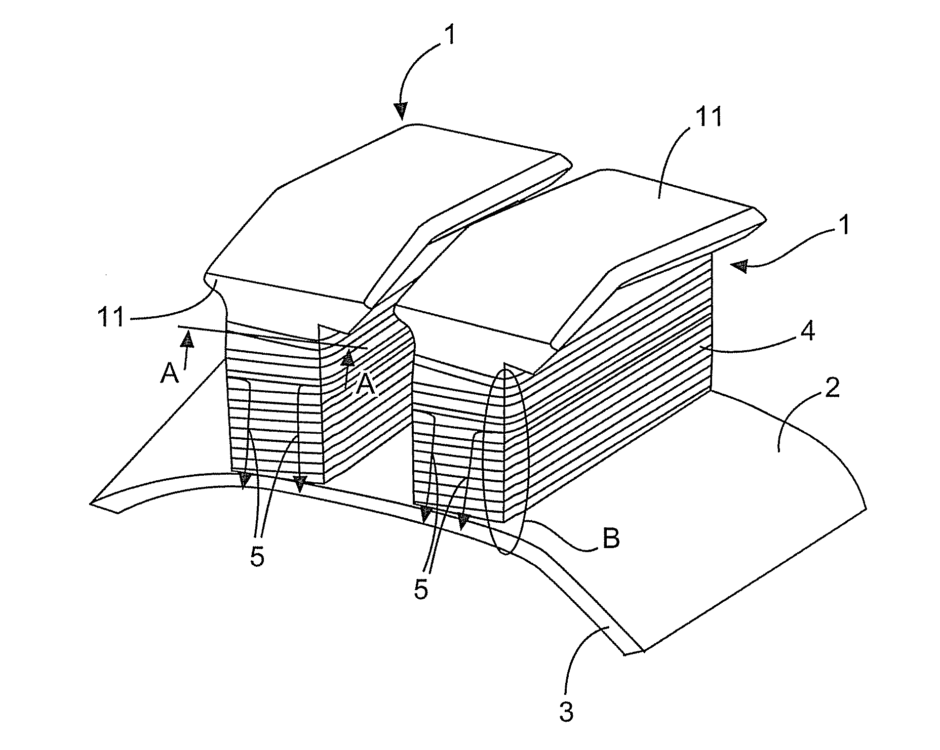
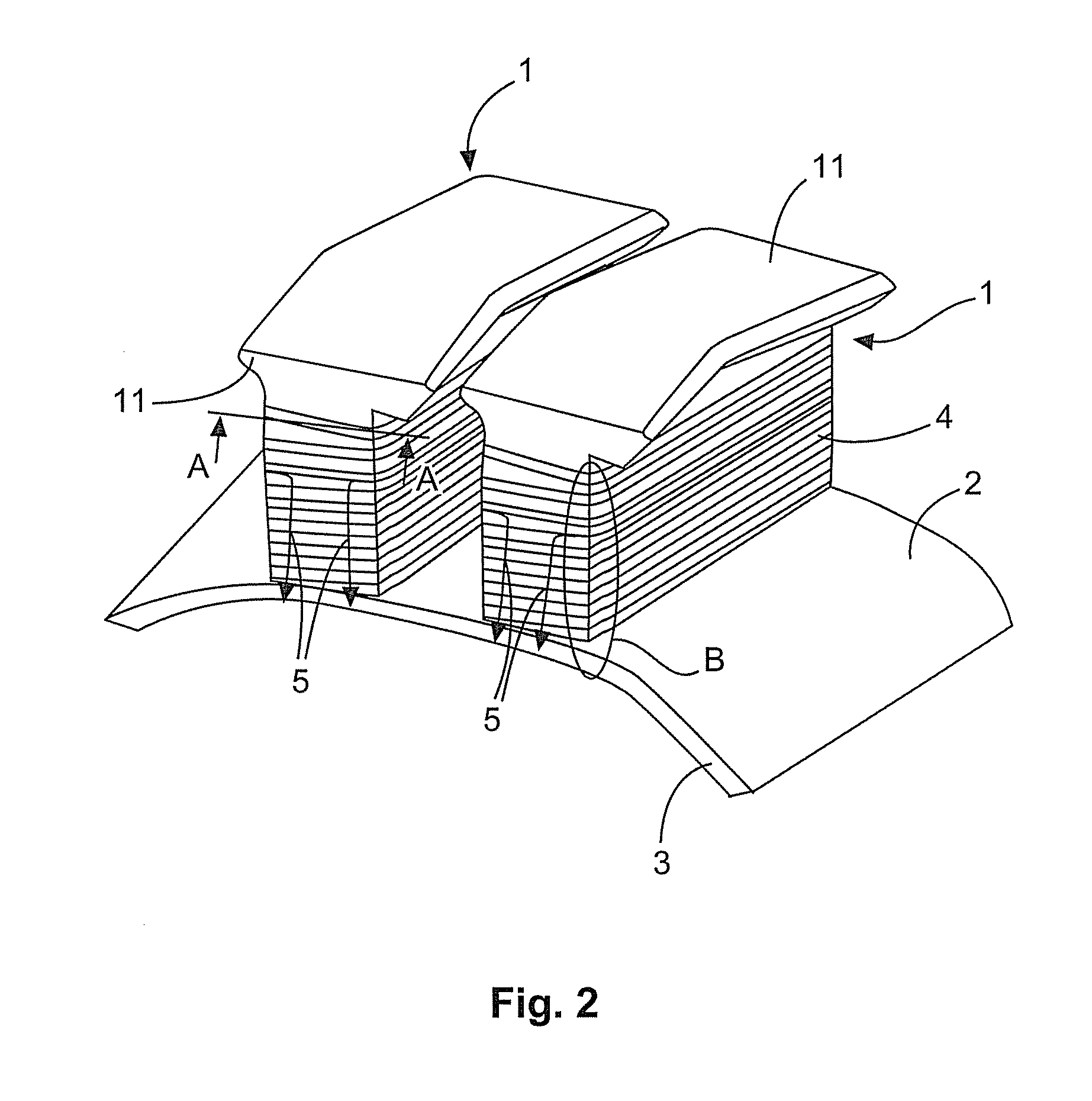
[0047]FIG....


PUM

PropertyMeasurementUnit
Electrical conductoraaaaaaaaaa
aaaaaaaaaa

Abstract

The invention relates to a laminated core assembly of an electric generator, in particular of a generator of a gearless wind turbine. The laminated core assembly comprises at least one laminated core, at least one winding arranged around the laminated core, and an electrical insulating means arranged between the laminated core and the winding, wherein the insulating means has a composite material for conducting the heat arising in the winding.

Description

BACKGROUND[0001]1. Technical Field[0002]The present invention relates to a laminated core assembly of an electric generator, in particular of a generator of a gearless wind turbine. The present invention relates further to an electric generator, in particular of a gearless wind turbine, as well as to a wind turbine. Furthermore, the present invention relates to a method for manufacturing a laminated core assembly.[0003]2. Description of the Related Art[0004]A pole shoe generally serves the purpose of leading a magnetic field and of[0005]letting the magnetic field lines exit in a defined form and distributing them. Such a pole shoe consists of a material with a high permeability. In an electric generator of a gearless wind turbine, pole shoes are, for example, located in the stator and / or in the rotor of the generator. In the following, pole shoe will mean a laminated pole shoe core, which, to prevent or to at least reduce eddy currents, is constructed of a number of different sheet ...

Claims


Application Information

Patent Timeline
IPC IPC(8): H02K9/22H02K15/04H01F41/02H02K9/02H02K3/34H02K1/20
CPCH02K9/22H01F41/02H02K9/02H02K15/04H02K3/345H02K1/20H02K3/325H02K7/1838Y10T29/49009H02K9/227H02K9/223H02K3/32
Inventor LENSCHOW, GERHARD
Owner WOBBEN PROPERTIES GMBH
Why Eureka
Try Eureka