Electronic component, power receiving device, and power feeding system

Inactive Publication Date: 2014-07-03
SEIKO INSTR INC
View PDF3 Cites 9 Cited by
  • Summary
  • Abstract
  • Description
  • Claims
  • Application Information

AI Technical Summary

Benefits of technology

[0015]According to the present invention, it is possible to appropr

Problems solved by technology

As described above, in the above-mentioned power feeding system, the battery can

Method used


Image

  • Electronic component, power receiving device, and power feeding system
  • Electronic component, power receiving device, and power feeding system
  • Electronic component, power receiving device, and power feeding system

Examples


Example

First Embodiment

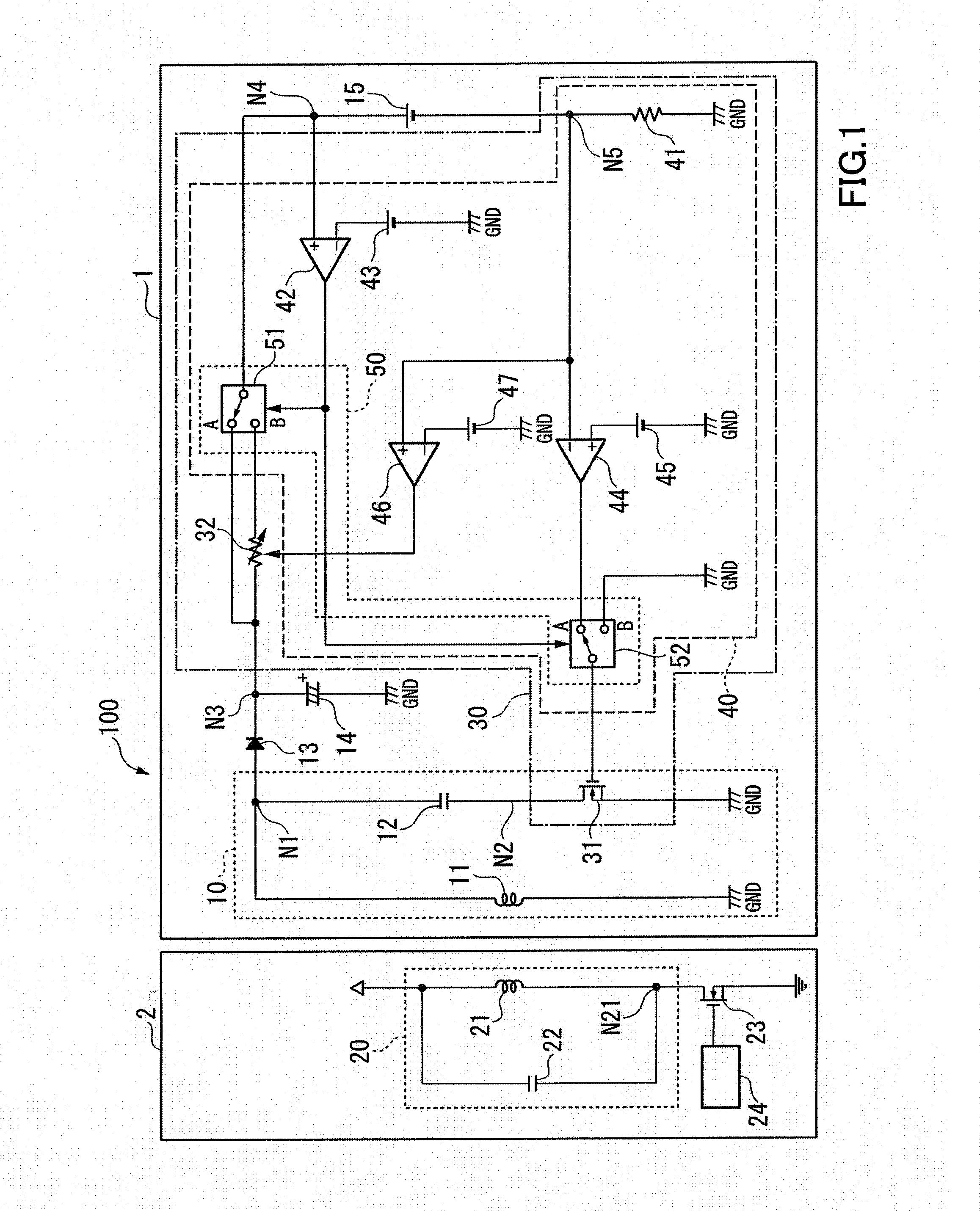
[0024]FIG. 1 is a schematic block diagram illustrating an exemplary power feeding system 100 according to a first embodiment of the present invention.

[0025]Referring to FIG. 1, the power feeding system 100 includes a power feeding device 2 and a power receiving device 1.

[0026]The power feeding system 100 is a system for supplying electric power from the power feeding device 2 to the power receiving device 1 by wireless (in a contactless manner). For example, the power feeding system 100 supplies electric power for charging a battery 15 included in the power receiving device 1 from the power feeding device 2 to the power receiving device 1. The power receiving device 1 is, for example, electronic equipment such as a mobile phone terminal or a PDA. The power feeding device 2 is, for example, a charger compatible with the power receiving device 1.

[0027]The power feeding device 2 includes a power feeding coil 21, a resonant capacitor 22, a drive transistor 23, and an osc...

Example

[0113]Next, a second embodiment according to the present invention is described below with reference to the accompanying drawings.

Second Embodiment

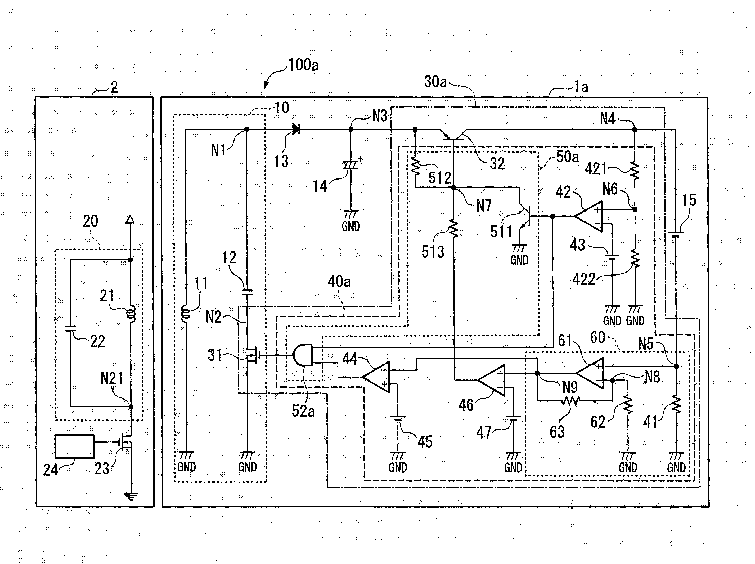
[0114]FIG. 6 is a schematic block diagram illustrating an exemplary power feeding system 100a according to the second embodiment of the present invention. In FIG. 6, the same configurations as in FIG. 1 are denoted by the same reference symbols, and descriptions thereof are omitted.

[0115]Referring to FIG. 6, the power feeding system 100a includes a power feeding device 2 and a power receiving device 1a.

[0116]The power feeding system 100a is a system for supplying electric power from the power feeding device 2 to the power receiving device 1a by wireless (in a contactless manner). For example, the power feeding system 100a supplies electric power for charging a battery 15 included in the power receiving device 1a from the power feeding device 2 to the power receiving device 1a.

[0117]The power receiving device 1a includes a power receivin...


PUM


Abstract

An electronic component includes: a switching element to be connected to a resonant circuit, the resonant circuit including a power receiving coil to be supplied with power from a power feeding coil and a resonant capacitor configured to resonate with the power receiving coil, in which the switching element is to be connected in parallel to the power receiving coil together with the resonant capacitor and connected in series to the resonant capacitor; a transistor to be connected in series to a battery that is charged by DC power obtained by the power receiving coil; a charge control section for controlling a current flowing through the transistor so that a charge current flowing through the battery matches with a given current value by setting the switching element to a non-conductive state when an output voltage of the battery is equal to or less than a given threshold voltage.

Description

BACKGROUND OF THE INVENTION[0001]1. Field of the Invention[0002]The present invention relates to an electronic component, a power receiving device, and a power feeding system.[0003]2. Description of the Related Art[0004]In recent years, there has been known a power feeding system for supplying electric power by wireless via electromagnetic induction or electromagnetic coupling between a power feeding coil and a power receiving coil, for example, in order to charge a battery included in electronic equipment such as a mobile phone terminal or a personal digital assistant (PDA). In such a power feeding system, a power receiving device on the receiving side includes a power receiving coil and a resonant capacitor that resonates with the power receiving coil, and, when an overcurrent flows, the power receiving device controls the resonant capacitor to be electrically disconnected in order to limit a current for charging a battery (see, for example, Japanese Patent Application Laid-open N...

Claims


Application Information

Patent Timeline
IPC IPC(8): H02J7/02H02J7/00
CPCH02J7/025H02J50/12
Inventor OKAZAKI, NORIHIRO
Owner SEIKO INSTR INC
Why Eureka
Try Eureka