Power inductor and method of manufacturing the same

a technology of power inductor and manufacturing method, which is applied in the direction of magnets, inductances, magnetic bodies, etc., can solve the problems of deterioration of high frequency characteristics, increased eddy current loss and hysteresis loss at a high frequency, and inability to implement the high current characteristics required in a recent electronic product. achieve excellent inductance and improve reliability

Active Publication Date: 2014-07-03
SAMSUNG ELECTRO MECHANICS CO LTD
View PDF4 Cites 77 Cited by
  • Summary
  • Abstract
  • Description
  • Claims
  • Application Information

AI Technical Summary

Benefits of technology

[0018]An aspect of the present invention provides a power inductor having exc...

Problems solved by technology

However, in a case in which the number of windings is increased in order to obtain high inductance, stray capacitance between coils, that is, capacitance between conducting wires maybe generated, such that high frequency characteristics are deteriorated.
However, this ferrite material has a saturation magnetization value lower than that of metal, such that high current characteristics required in a recent electronic product may...

Method used


Image

  • Power inductor and method of manufacturing the same
  • Power inductor and method of manufacturing the same
  • Power inductor and method of manufacturing the same

Examples


Embodiment Construction

[0045]Hereinafter, embodiments of the present invention will be described in detail with reference to the accompanying drawings. The invention may, however, be embodied in many different forms and should not be construed as being limited to the embodiments set forth herein. Rather, these embodiments are provided so that this disclosure will be thorough and complete, and will fully convey the scope of the invention to those skilled in the art. In the drawings, the shapes and dimensions of elements may be exaggerated for clarity, and the same reference numerals will be used throughout to designate the same or like elements.

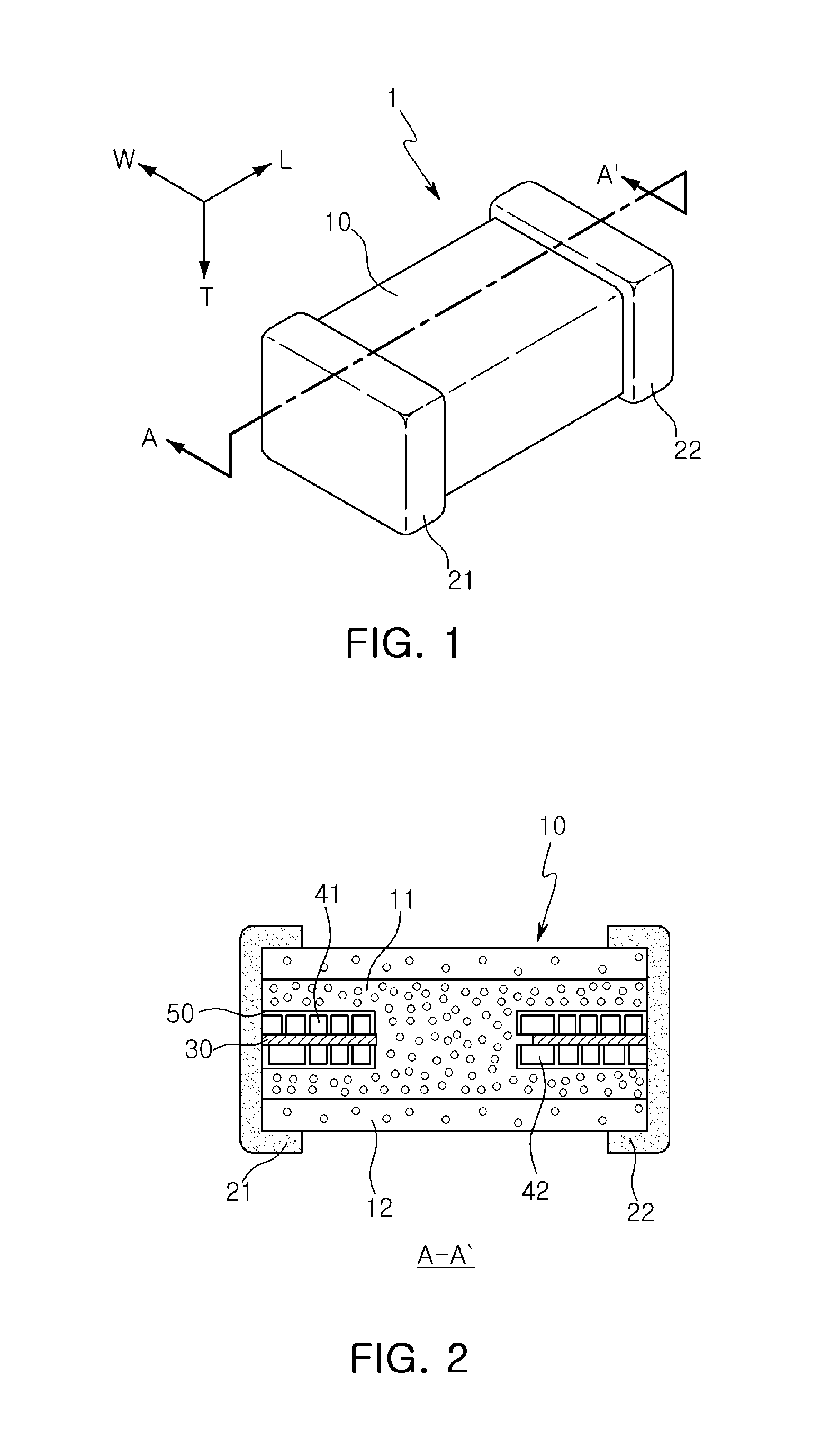
[0046]FIG. 1 is a perspective view showing a schematic structure of a power inductor according to an embodiment of the present invention.

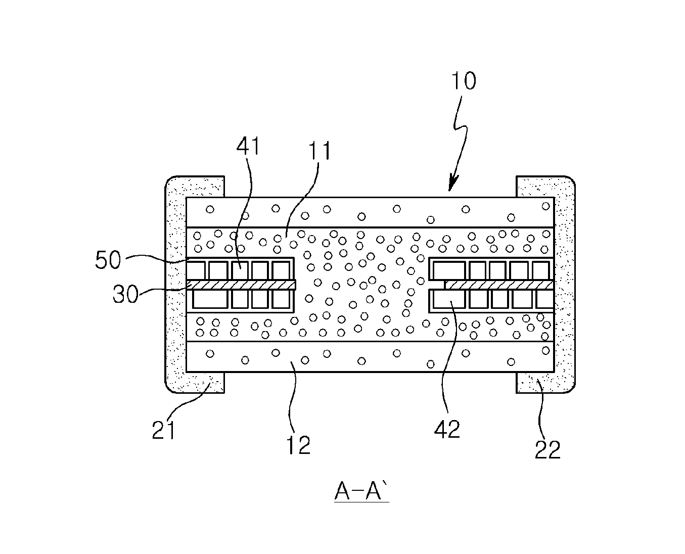
[0047]FIG. 2 is a cross-sectional view schematically showing the power inductor taken along line A-A′ of FIG. 1.

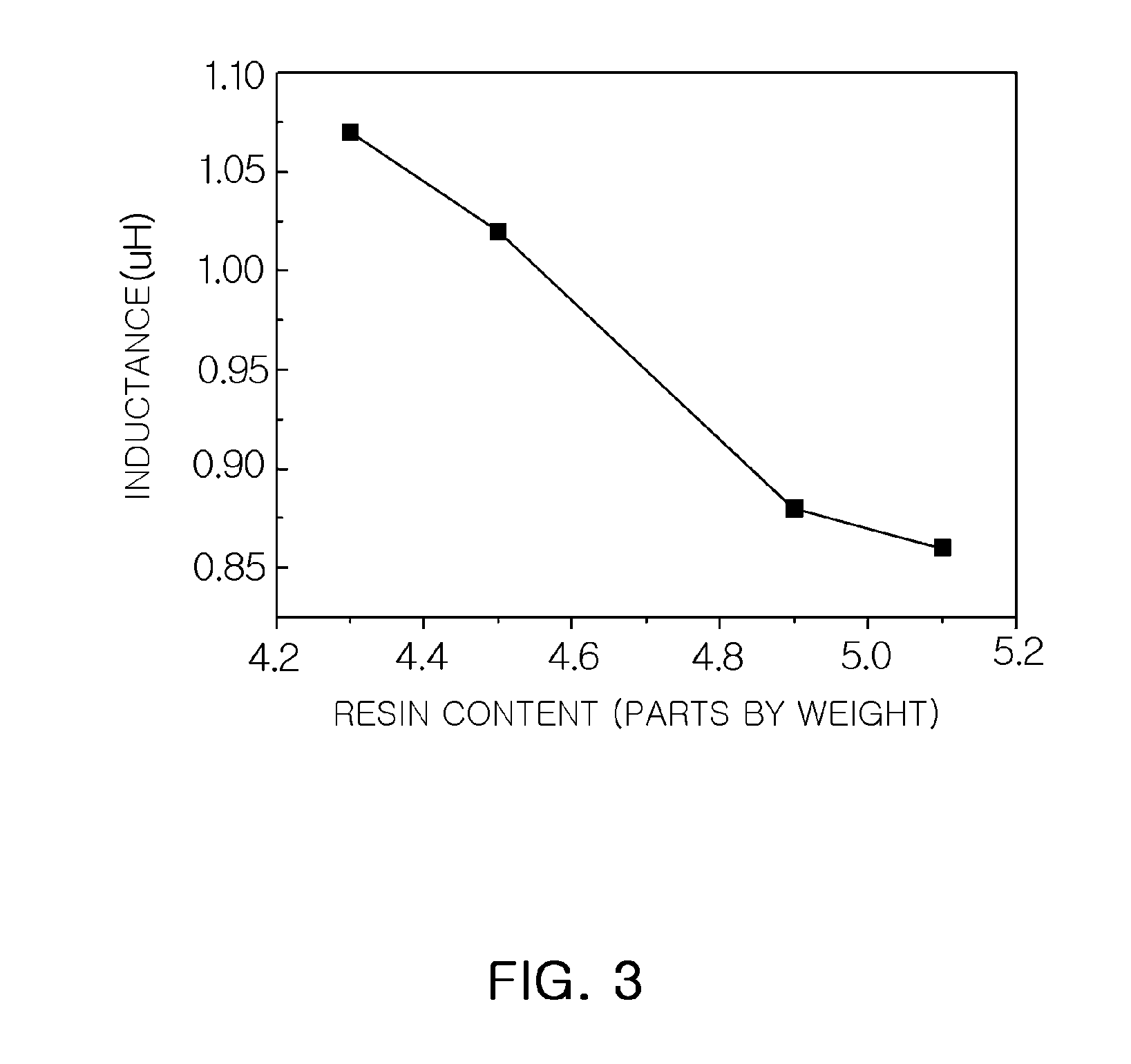
[0048]FIG. 3 is a graph showing the change in inductance as compared with the content of polymer resin.

[0049]Referring ...


PUM

PropertyMeasurementUnit
Percent by massaaaaaaaaaa

Abstract

There is provided a power inductor, including a magnetic body including a substrate having coils formed thereon, a first metal-polymer complex layer formed on upper and lower surfaces of the substrate, and a second metal-polymer complex layer formed on upper and lower surfaces of the first metal-polymer complex layer and including a higher content of a polymer than that included in the first metal-polymer layer.

Description

CROSS-REFERENCE TO RELATED APPLICATIONS[0001]This application claims the priority of Korean Patent Application No. 10-2012-0155965 filed on Dec. 28, 2012, in the Korean Intellectual Property Office, the disclosure of which is incorporated herein by reference.BACKGROUND OF THE INVENTION[0002]1. Field of the Invention[0003]The present invention relates to a power inductor having excellent inductance characteristics and improved reliability, and a method of manufacturing the same.[0004]2. Description of the Related Art[0005]Examples of electronic components using a ceramic material include a capacitor, an inductor, a piezoelectric element, a varistor, a thermistor, and the like.[0006]Among these ceramic electronic components, an inductor, an important passive element configuring an electronic circuit, together with a resistor and a capacitor, may mainly be used as a component for removing noise or configuring an LC resonance circuit.[0007]An inductor may be manufactured by winding coil...

Claims


Application Information

Patent Timeline
IPC IPC(8): H01F27/255H01F41/00
CPCH01F41/00H01F27/255H01F17/0013H01F41/046H01F2017/048Y10T29/4902H01F1/14791
Inventor PARK, MOON SOOLEE, HWAN SOOCHA, HYE YEON
Owner SAMSUNG ELECTRO MECHANICS CO LTD
Why Eureka
Try Eureka