Method for measuring concentration of a gas component in a measurement gas

Active Publication Date: 2014-07-03
SIEMENS AG
View PDF9 Cites 11 Cited by
  • Summary
  • Abstract
  • Description
  • Claims
  • Application Information

AI Technical Summary

Benefits of technology

[0009]It is an object of the invention to increase the accuracy and reliability of a measurement in the c

Problems solved by technology

However, in the case of higher concentrations, the approximations required to evaluate the measurement signal become increasingly inaccurate, and so th

Method used


Image

  • Method for measuring concentration of a gas component in a measurement gas
  • Method for measuring concentration of a gas component in a measurement gas
  • Method for measuring concentration of a gas component in a measurement gas

Examples


Embodiment Construction

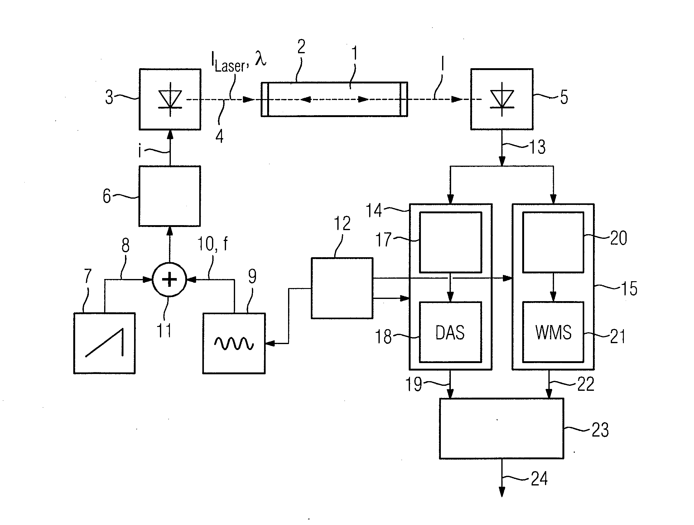
[0026]FIG. 1 is a schematic of a laser spectrometer for measuring the concentration of at least one gas component of interest for a measurement gas 1, which is contained in a measurement volume 2, such as a measurement cell or a process gas line. The spectrometer includes a laser diode 3 whose light 4 falls onto a detector 5 after radiating through the measurement gas 1. The laser diode 3 is driven by a controllable current source 6 with an injection current i, the intensity ILaser and wavelength λ of the generated light 4 being a function of the current i and the operating temperature of the laser diode 3. The current source 6 is driven by a first signal generator 7 periodically with the aid of a prescribed current / time function 8, preferably in the shape of a ramp or triangle, in order to scan a selected absorption line of the gas component of interest with the aid of the wavelength λ of the generated light 4, which more or less follows the profile of the current i. A second signa...


PUM


Abstract

A method in which the wavelength of the light of a tunable light source is varied periodically over an absorption line of interest for the gas component to measure the concentration of a gas component in a measurement gas based on one of two measurement methods of direct absorption spectroscopy and wavelength modulation spectroscopy and, where in the case of wavelength modulation spectroscopy, the wavelength of the light is additionally sinusoidally modulated at a high frequency and with a small amplitude, where the intensity of the light is detected after transradiation of the measurement gas and processed to yield a measurement result, and where in order to increase the accuracy and reliability of the measurement, the two measurement methods are applied simultaneously during each period, or alternately in consecutive periods, and their results are combined by averaging to form the measurement result.

Description

BACKGROUND OF THE INVENTION[0001]1. Field of the Invention[0002]The invention relates to a method for measuring concentration of a gas component based on two measurement methods of direct absorption spectroscopy and wavelength modulation spectroscopy, where the wavelength of the light of a tunable light source is varied periodically over an absorption line of interest for the gas component and, in the case of wavelength modulation spectroscopy, the wavelength of the light is additionally sinusoidally modulated at a high frequency and with a small amplitude, and the intensity of the light is detected after transradiation of the measurement gas and processed to yield a measurement result.[0003]2. Description of the Related Art[0004]DE 102 38 356 A1 discloses a method in which two measurement methods are applied alternately in consecutive periods.[0005]Laser spectrometers are used, in particular, for optical gas analysis in process measurement technology. In this case, a laser diode ge...

Claims


Application Information

Patent Timeline
IPC IPC(8): G01J3/433G01J3/42
CPCG01J3/42G01J3/433G01N21/39G01J3/4338G01N21/47
Inventor DEPENHEUER, DANIELHANKIEWICZ, THOMASPROBST, FRANK
Owner SIEMENS AG
Why Eureka
Try Eureka