Storage screens for medical radiography

a technology for storage screens and radiography, applied in the field of phosphor storage screens, can solve the problems of yellowing of screens, unsatisfactory appearance for users, weary appearance of screens, etc., and achieve the effect of preventing yellowing of screens in an efficient and simple manner

Active Publication Date: 2014-07-03
AGFA NV
View PDF1 Cites 0 Cited by
  • Summary
  • Abstract
  • Description
  • Claims
  • Application Information

AI Technical Summary

Benefits of technology

[0035]It is an object of the present invention to provide a method for producing and treating storage phosphorus screens for radiography that allow to solve the above mentioned drawbacks in an efficient and simple manner. In particular, it is proposed a method for producing and treating phosphor screens having iodine in their composition that prevents the yellowing of said screens.

Problems solved by technology

In the case of phosphor screens using phosphor powder compounds incorporating iodine, in the course of its use, a yellowing of the screens occur.
A drawback occasioned by such yellowing is that such screen is characterized by an unpleasing appearance for the user; it also gives to said screen a weary appearance.
A further and more technical disadvantage is that when the screen is read out in a digitizer, an uneven or stained image is detected.
This is the main disadvantage, since it compromises use of the plate for (medical) diagnosis.
The visual result is a noticeable yellowing of the screen.
This is clearly unacceptable since the quality of the medical diagnosis is negatively influenced by this event.
The yellowing problem of the phosphor screens and the resulting local weakening of the emission light occurs not only in the case of phosphor screens used for general radiography (e.g. for exposure of the lungs or the thorax) but for special radiographic applications such as mammography as well.
In case of using said phosphor screens for non-destructive testing this is also a disadvantage.
However, this situation is a major issue when such phosphor screens are meant to be used in dental applications.
Therefore, no shield from light is provided in such cases.
Besides, the treatment herein described is superficial and takes place at a time that the yellowing problem has already occurred and cannot be solved any more.
In fact, as soon as the gaseous iodide has been formed in the phosphor layer, the yellowing problem occurs and cannot be remedied any more by a later superficial treatment of the phosphor layer.
Most of the examples cited in the text are directed to a resin, which reactivity is inherently limited.
However, in quite a number of cases this is impossible because the phosphor layer quickly dries after coating.
Therefore, the resin molecules are in fact immobilised in the phosphor layer and as a result of this they become useless for the aim as set forth above.
This phenomenon and resulting disadvantage is even stronger when the resin molecules are present in a layer neighbouring the phosphor layer instead of being present in the phosphor layer itself.
However, in this case another drawback arises, namely the evaporation of low-molecular weight epoxy containing compounds during the coating- and drying operations of the phosphor layer.
As result, the gain occasioned by the use of more reactive low-molecular weight compounds is lost through the loss of such compounds of the phosphor mixture, due to the evaporation of such compounds from the coated phosphor layer.
The practical result of this is that the still present reactive iodide at the surface of the phosphor particle after coating and drying of the phosphor layer, cannot be ‘treated’ by the still present immobile epoxides in such layer.
Eventually, this gives raise to yellowing phenomenon of the screens causing the problems as described above.
A second disadvantage of this method is that the presence of such extra component reduces the packing density of the phosphor screen; this packing density should be as high as possible in case of stimulable phosphor screens.
A third disadvantage of this method is that the presence of such extra component negatively influences the drying characteristics of the phosphor layer in production.
This, in turn leads to screen structure and variations in packing density.
Finally, there is still another important disadvantage linked to method disclosed in EP 0 234 385: working with such resins, which comprise toxic components raise a number of issues in practical working conditions, ex. from the point of view of safety of the installations, such as increasing the risk of explosion and, from the point of view of the operating staff increased health risk due to carcinogenic components.

Method used


Image

  • Storage screens for medical radiography

Examples


Embodiment Construction

[0038]The present invention relates to a method for producing and treating a storage phosphorus screen for radiography wherein said phosphorous screen comprises a phosphorous composition containing iodine and wherein a treatment with at least an epoxy group containing compound in gaseous form is applied to said phosphorous composition.

[0039]It is believed that the treatment of phosphor screens with at least a compound comprising at least an epoxy group results in a nucleophylic substitution by the strongly nucleophylic iodide on the epoxy compound.

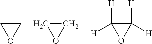
[0040]Because a phosphor layer upon coating and drying can contain up to 30% by volume of air, the epoxy compound molecules can relatively easily enter such porous phosphor screens and exert its function. In the case of oxirane, it is thought that probably the triangle opens up and interacts with the surface of the phosphor particle. Probably the following compound is formed: I—(CH2—CH2—O—)n—H with n≧0.

[0041]As mentioned before, typically ...


PUM

PropertyMeasurementUnit
shapesaaaaaaaaaa
compositionaaaaaaaaaa
thicknessaaaaaaaaaa

Abstract

The present invention concerns a method for the treatment of stimulable phosphors and/or screens for use in diagnosis, in particular medical radiography. The method comprises subjecting the stimulable phosphors and/or screens to an epoxide containing gaseous compound, promptly following their manufacture. By applying the method according to the invention yellowing of the stimulable phosphors and/or screens is prevented in a safe and efficient manner; thereby the disadvantages known as such resulting from such yellowing will not occur.

Description

CROSS-REFERENCE TO RELATED APPLICATIONS[0001]This patent application is a U.S. National Phase Patent Application of International Patent Application No. PCT / EP2012 / 059559, filed May 23, 2012, which claims the benefit of Belgian Patent Application No. 2011 / 0318, filed May 24, 2011, both of which are incorporated by reference in their entireties.FIELD OF THE INVENTION[0002]The present invention relates to a method for the production of phosphor storage screens for use in diagnosis, more in particular for use in medical radiography. The treatment of screens according to the present invention takes place during and after the production of such screens. According to the method of the invention the so-produced screens are treated with an epoxides compound such as oxirane so as to prevent yellowing of the screens in a later stage, and the problems related with such yellowing.[0003]The method according to the invention is likewise applicable to semi-finished products in the production of sc...

Claims


Application Information

Patent Timeline
Patent Type & Authority Applications(United States)
IPC IPC(8): A61B6/00
CPCA61B6/4216G21K4/00
Inventor LEBLANS, PAULTAHON, JEAN-PIERRE
Owner AGFA NV
Why Eureka
Try Eureka