

Electricity suppressing type electricity and heat optimizing control device, optimizing method, and optimizing program
- Summary
- Abstract
- Description
- Claims
- Application Information
AI Technical Summary
Benefits of technology
Problems solved by technology
Method used
Image

Examples
first embodiment
A. First Embodiment
1. Brief Summary of Electricity and Heat Storage Optimizing System
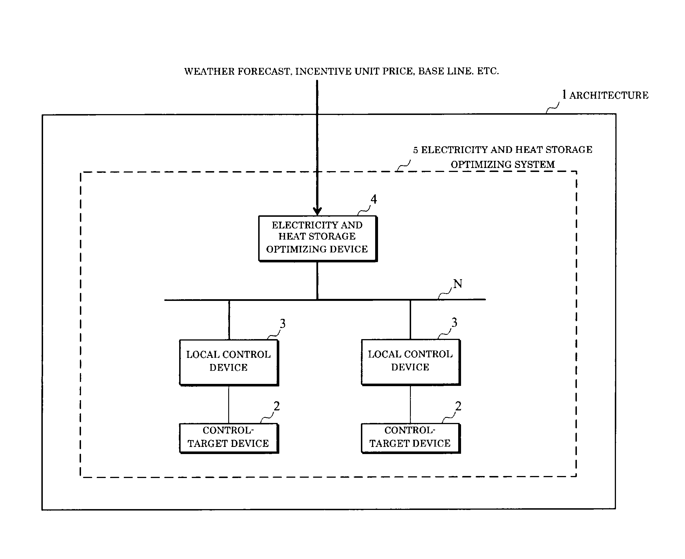
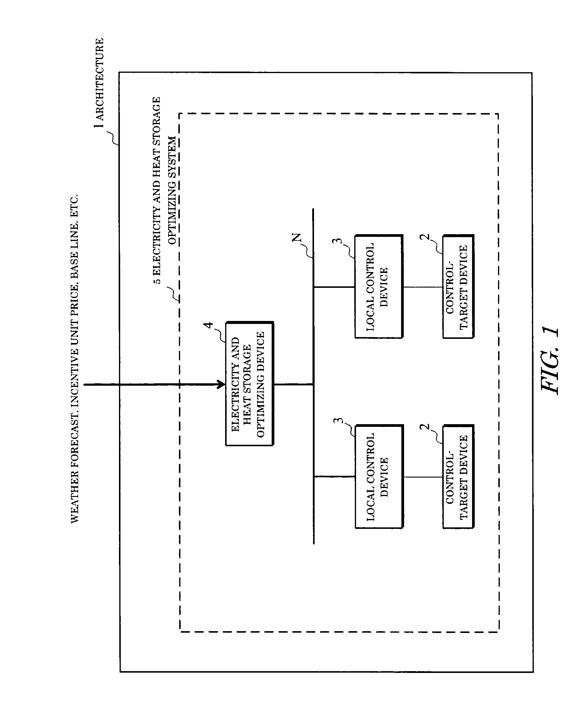
[0042]As illustrated in FIG. 1, an electricity and heat storage optimizing system 5 according to this embodiment includes various control-target devices 2, local control devices 3 and an electricity and heat optimizing control device 4 all placed in a target architecture 1.
[0043]The control-target devices 2 include at least one of an energy consuming device, an energy supplying device, and an energy storing device. The energy consuming device is a device that consumes supplied energy. For example, the energy consuming device includes an air conditioning device (air conditioner), a lighting device, and a heat source device.
[0044]The energy supplying device is a device that supplies energy to the energy consuming device and the energy storing device. For example, the energy supplying device includes a solar power generator (PV), and a solar water heater.
[0045]The energy storing device is a device that...
second embodiment
B. Second Embodiment
1. Configuration
[0247]The configuration of this embodiment is basically the same as that of the above-explained first embodiment. However, the preference order of the determination time determined by the determination time setter 122 in the incentive acceptance determiner 12 is different. That is, according to this embodiment, the determination time is set in an order that the value of the predicted electricity consuming energy predicted by the energy predictor 10 is smaller.
2. Action
[0248]The action of the above-explained this embodiment is basically the same as that of the above-explained first embodiment. When, however, the operating schedule is planned, in the step 12 in the flowchart of FIG. 9, the determination time setter 122 sets the determination time in an order that the predicted consumed energy set by the energy predictor 10 is smaller.
[0249]FIG. 12 illustrates an example preference order of the incentive acceptance determination time set in this mann...
third embodiment
C. Third Embodiment
1. Configuration
[0252]The configuration of this embodiment is basically the same as that of the above-explained first embodiment. In this embodiment, however, as illustrated in FIG. 13, a preference order inputter 25 is provided. The preference order inputter 25 is a processor to input a preference order regarding at which time the user preferentially performs electricity suppression.
[0253]The preference order inputter 25 may be commonly implemented as the above-explained inputter. In addition, the preference order inputter 25 may be configured as a processing unit that accepts a preference order input through the transmitter / receiver 24 and sets the preference order in the process data memory 22. Still further, the input / output terminal of the user connected to the transmitter / receiver 24 via the network N is also included as the preference order inputter 25.
2. Action
[0254]The action of the above-explained this embodiment is basically the same as that of the abov...
PUM
 Abstract
Description
Claims
Application Information