Lightened Rotating Member and Method of Producing Same

a rotating member and light-weight technology, applied in the field of positive displacement pump and engine recovery, can solve the problems of increasing the cost of operators, exceedingly heavy, and extreme rock pressure beneath the earth's surface, so as to reduce the torsional stability and balance of the rotating member, and reduce the inertia of the rotating member

Inactive Publication Date: 2014-07-17
FTS INT SERVICES
View PDF2 Cites 43 Cited by
  • Summary
  • Abstract
  • Description
  • Claims
  • Application Information

AI Technical Summary

Benefits of technology

[0015]Disclosed herein is a lightened rotating member for a machine, the rotating member comprising: a plurality of radial penetrations, the radial penetrations formed around the circumference of at least one main bearing support journal. Another embodiment includes a plurality of radial penetrations, the radial penetrations formed around the circumference of each of a plurality of main bearing support journals. In another embodiment the radial penetrations are blind holes. In another embodiment the radial penetration centerlines are evenly spaced around the circumference. In another embodiment that includes an even number of evenly-spaced radial penetrations, there is at least one radial penetration dimension that differs in response to dynamic balancing of the rotating member. In another embodiment one or more grooves are formed around the circumference of the at least one main bearing support journal. Another embodiment includes a bearing race that is independently positional about the penetrated bearing support journal. Another embodiment includes a bearing race that is independently positional about the penetrated bearing support journal, wherein positioning of the bearing race substantially conceals the radial penetrations. In another embodiment the radial penetrations are configured to reduce the inertia of the rotating member without substantially reducing the torsional stability and balance of the rotating m

Problems solved by technology

Rock pressures beneath the earth's surface are quite extreme, especially given the depths to which the well holes must be drilled to reach the pay zones.
To handle such extreme operating conditions, each of these components must typically be forged from high strength alloy steel and, consequently, is exceedingly heavy.
In fact, it is not uncommon for such a tractor/trailer combination to weigh as much

Method used


Image

  • Lightened Rotating Member and Method of Producing Same
  • Lightened Rotating Member and Method of Producing Same
  • Lightened Rotating Member and Method of Producing Same

Examples


Embodiment Construction

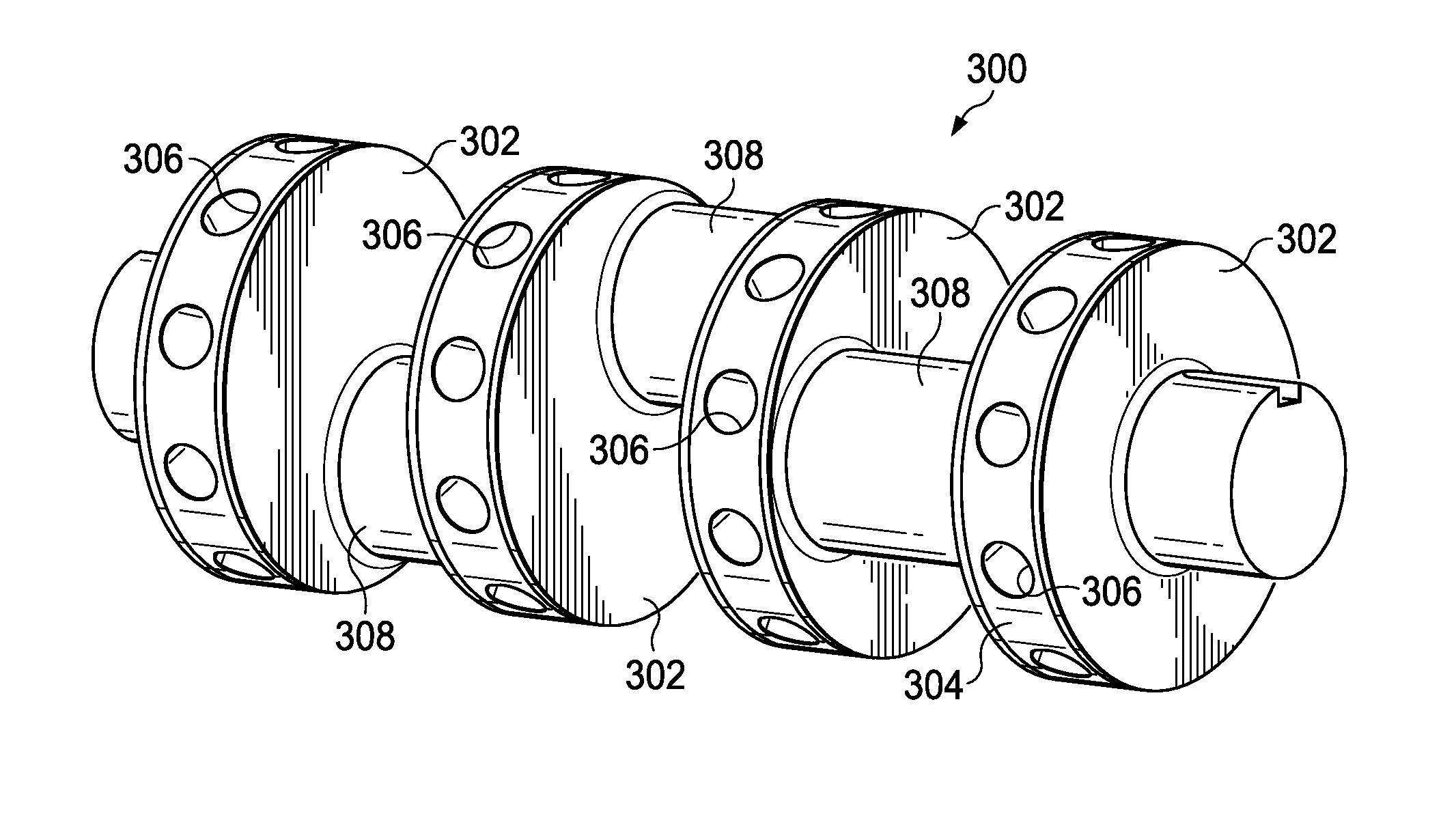
[0026]FIG. 3 depicts a perspective view of a first embodiment of a rotating member utilizing the present invention in the form of a crankshaft rotating-member separated from the power end housing of a frac pump. As shown, the crankshaft (300), in triplex configuration, features three rod bearing journals (308) supported by four main bearing journals (302). The main bearing journals have a bearing face (304) upon which an inner bearing race is mounted for a roller main bearing assembly (see FIG. 6). A plurality of blind hole penetrations (306) is formed in each bearing face (304) along the circumferential centerline. Although a triplex configuration is described for the present embodiment, other embodiments are possible and the same principles apply. For example, in a quintuplex configuration the crankshaft would have five rod bearing journals supported by at least six main bearing journals. One of ordinary skill in the art to which the invention pertains will appreciate that a rotat...


PUM

PropertyMeasurementUnit
Dimensionaaaaaaaaaa
Weightaaaaaaaaaa
Circumferenceaaaaaaaaaa

Abstract

A lightened rotating member for a machine. The lightened member includes a plurality of radially machined penetrations within at least one main bearing support journal of the rotating member. The plurality of penetrations is formed around the circumference of the main bearing journal face, with the penetration centerline directed radially toward the rotating member's axial centerline. An even number of penetrations may be utilized with minimal adverse effect on the balance of the rotating member. Odd numbers of penetrations may require subsequent rebalancing. The rotating member may be any rotating member that utilizes one or more main bearing support journals.

Description

CROSS-REFERENCE TO RELATED APPLICATIONS[0001]Not ApplicableSTATEMENT REGARDING FEDERALLY SPONSORED RESEARCH OR DEVELOPMENT[0002]Not ApplicableTHE NAMES OF THE PARTIES TO A JOINT RESEARCH AGREEMENT[0003]Not ApplicableINCORPORATION-BY-REFERENCE OF MATERIAL SUBMITTED ON A COMPACT DISC[0004]Not ApplicableBACKGROUND OF THE INVENTION[0005]1. Field of the Invention[0006]The present invention relates to reciprocating positive-displacement pumps and engines and, more specifically, to lightened rotating members within positive displacement pumps and engines and methods of producing same.[0007]2. Description of Related Art including information disclosed under 37 CFR 1.97 and 1.98[0008]Horizontal drilling and well stimulation processes have revolutionized the oil and gas industry with regard to the optimization of hydrocarbon extraction. Shale areas once thought unreachable are now within range of the horizontal drilling technology, with most shale gas wells having an average depth from the su...

Claims


Application Information

Patent Timeline
IPC IPC(8): F16C3/06B23P17/00
CPCB23P17/00F16C3/06F16C3/08F16C9/02F16C19/26Y10T74/2183Y10T29/49826Y10T29/49
Inventor SMALL, TONY M.PATEL, PANKAJ
Owner FTS INT SERVICES
Why Eureka
Try Eureka