
Air treatment device

a technology of air treatment device and air purification unit, which is applied in the direction of transportation and packaging, lighting and heating apparatus, heating types, etc., to achieve the effect of increasing the operating speed of the air purifying uni

Active Publication Date: 2014-07-17
KONINKLIJKE PHILIPS ELECTRONICS NV
View PDF1 Cites 5 Cited by
  • Summary
  • Abstract
  • Description
  • Claims
  • Application Information

AI Technical Summary

Benefits of technology

The air treatment device described in the patent allows for the control of scent dispensing and air purification speed based on the detected air quality. This means that when the air quality is poor, the device can speed up the purification process and reduce the amount of scent dispensed, while when the air quality is good, the device can slow down the purification process and increase the amount of scent dispensed. This results in a faster improvement of air quality and a pleasanter smell for the user.

Problems solved by technology

This issue becomes serious when the dispensing flow of scent is kept constant over a long period of time, or even severe when the dispensing flow of scent and the fan speed of the air purifier increase simultaneously.

Method used


Image

  • Air treatment device
  • Air treatment device

Examples


Embodiment Construction

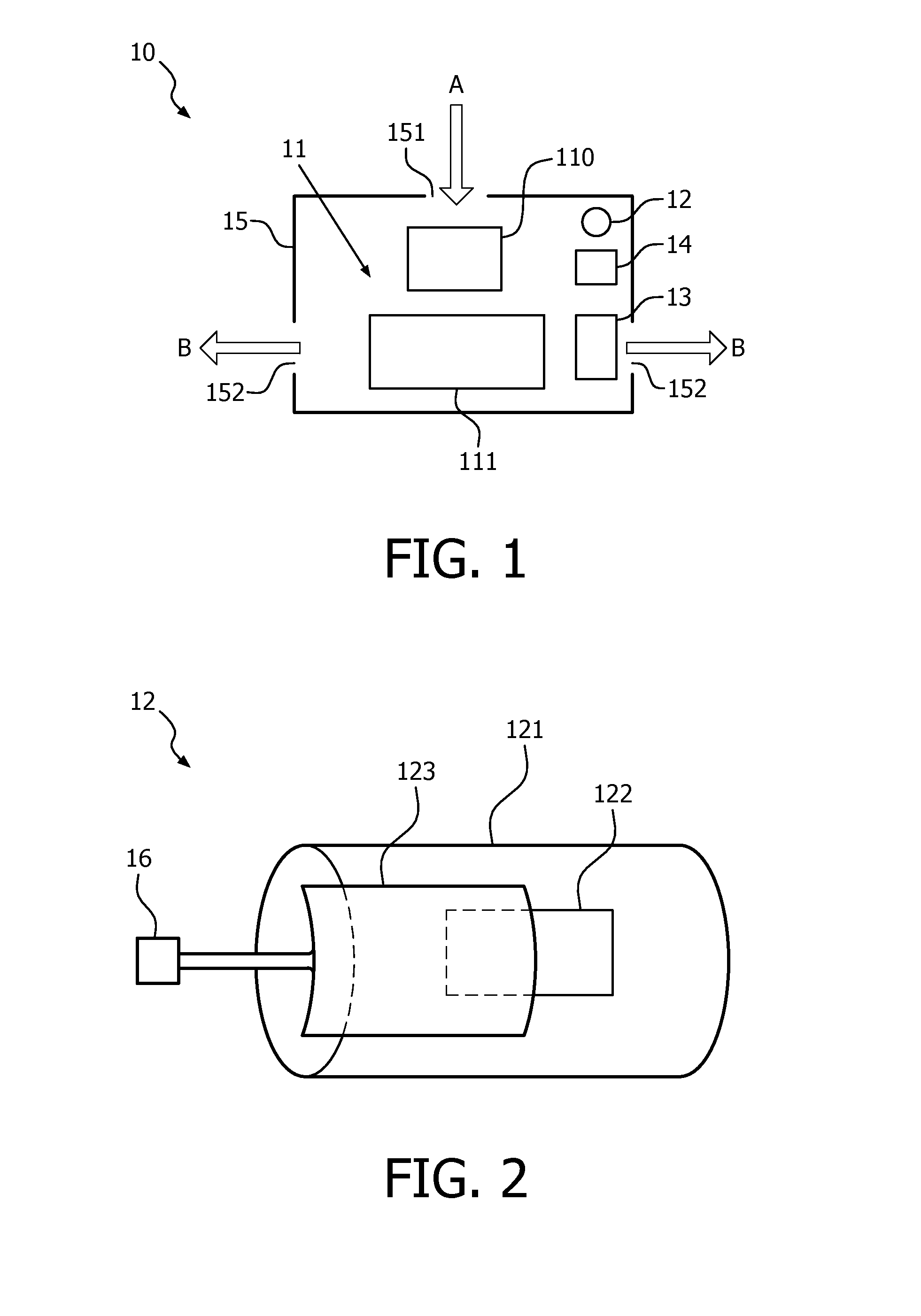
[0026]FIG. 1 depicts an exemplary air treatment device according to one aspect of the invention. The exemplary air treatment device 10 may generally be used in home, office, automobile or other places of interest, to purify air.

[0027]Referring to FIG. 1, the air treatment device 10 comprises an air purifying unit 11 configured to purify air. The air purifying unit 11 may take on various configurations, but it generally includes a filtering unit 110 and an impeller 111. The filtering unit 110 may typically include a particle filter for filtering particles, such as dust from passing air for example, and a gas filter for filtering gases, such as chemical gases from passing air for example. The impeller 111 is configured to force the air to be purified to pass through the filtering unit 110, which may be a backward impeller or a forward impeller for example. In this embodiment, the operating speed of the air purifying unit 11, i.e. the fan speed of the impeller 111, is controllable and ...


PUM

PropertyMeasurementUnit
speedaaaaaaaaaa
operating speedaaaaaaaaaa
lifetimeaaaaaaaaaa

Abstract

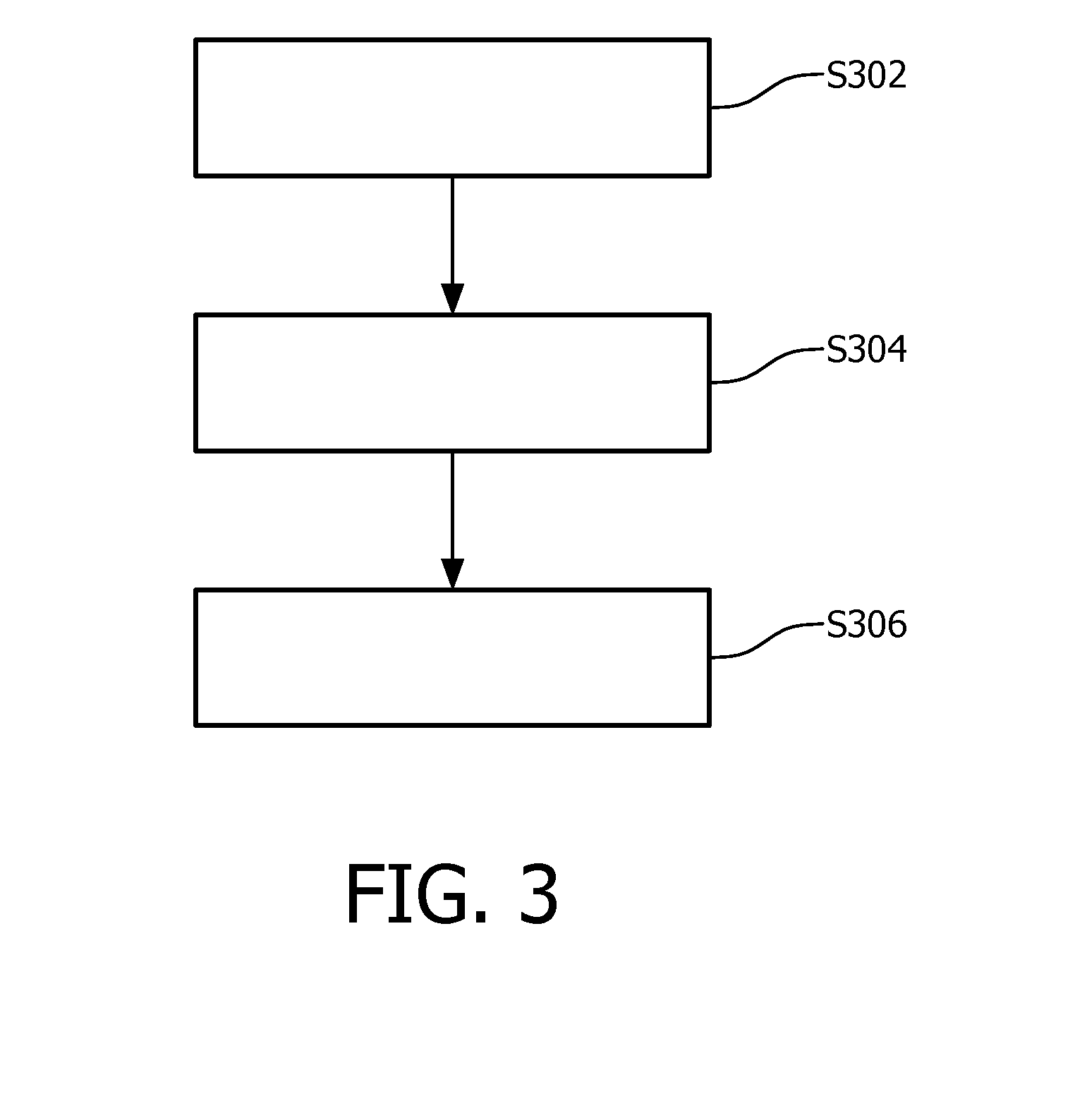
An embodiment of the invention provides an air treatment device. The air treatment device comprises an air purifying unit configured to purify air; a scent dispenser configured to dispense scent; an air detector, configured to detect the purified air and provide an output signal; and a processor configured to receive the output signal from the air detector and control the operation speed of the air purifying unit and the dispensing flow of scent dispensed by the scent dispenser, based on the output signal, wherein the dispensing flow of scent dispensed by the scent dispenser is decreased with the increase of the operating speed of the air purifying unit. Another embodiment of the invention provides a method of controlling a scent dispenser and an air purifying unit of an air treatment device, wherein the air treatment device further includes an air detector and a processor. The method comprises the steps of purifying air by using the air purifying unit; detecting the purified air by using the air detector; controlling, by using the processor, the operating speed of the air purifying unit and the dispensing flow of scent dispensed by the scent dispenser, based on the detection result, wherein the dispensing flow of scent dispensed by the scent dispenser is decreased with the increase of the operating speed of the air purifying unit.

Description

FIELD OF THE INVENTION[0001]The invention relates to the field of air treatment, in particular air treatment devices and methods used in the automotive industry.BACKGROUND OF THE INVENTION[0002]Urbanization and industrialization cause much air pollution in the megacities, especially those in emerging markets. To purify the ambient air in order to improve air quality, air purifiers are widely used in homes, offices and automobiles to remove, for example, dust, formaldehyde, volatile organic compounds (VOC), germs, etc. Moreover, scent dispensers are also popular; they are used to improve air quality in that they can help remove / conceal / mitigate offensive odors and thus improve people's emotional feelings.[0003]In the existing air purifiers, the scent dispenser is typically integrated with the air purifier to help provide a pleasant smell while purifying air. The air purifier and the scent dispenser mainly operate in the following two ways. In one approach, when the air purifier opera...

Claims


Application Information

Patent Timeline
Patent Type & Authority Applications(United States)
IPC IPC(8): A61L9/12
CPCA61L9/12A61L9/122A61L2209/11A61L2209/133A61L2209/14B60H3/0035B60H3/06B60H2003/0042B60H2003/0683F24F3/12F24F11/77F24F8/50Y02B30/70B60H3/00
Inventor SHEN, FANGZHONG
Owner KONINKLIJKE PHILIPS ELECTRONICS NV
Learn More