Systems and methods for fusing a sacroiliac joint and anchoring an orthopedic appliance

a technology of sacroiliac joints and orthopedic appliances, applied in the field of medical devices and methods, can solve the problems of limited or unconstrained movement, insufficient engagement of existing implant structures with the articular surfaces or cortical bone of the joint for adequate fixation or fusion, and the immobilization of the afflicted join

Active Publication Date: 2014-07-17
JCBD
View PDF3 Cites 118 Cited by
  • Summary
  • Abstract
  • Description
  • Claims
  • Application Information

AI Technical Summary

Benefits of technology

[0020]The anchor fitting may be attached to an anchor support element of the attachment assembly and configured to receive an anchor within a preselected range of anchor insertion trajectories. The anchor support element may include a rectangular cross-sectional profile and the anchor fitting may include a channel with a rectangular cross-sectional contour matched to the cross-sectional profile of the anchor suppor

Problems solved by technology

These existing fusion implants may completely immobilize the afflicted joint or may allow limited or unconstrained movement to approximate or permit the normal movements of the afflicted joint.
One limitation of many existing fusion procedures involves the challenge of situating a fusion implant in suitably close alignment with the removed tissues of the patient to achieve a stable fixation of the joint or vertebrae.
Existing implant structures may have insufficient engagement with the articular surfaces or cortical bone of the joint for adequate fixation or fusion.
This failure to sufficiently stabilize and fuse the joint with the conventional implant structures and methods may result in a failure to relieve the condition being treated.
Another limitation of the fusion and fixation implants and associated anchors used in existing fusion procedures is the relatively large profile or prominence of the components.
The large footprint of existing fusion implants and associated anchors necessitate the removal of considerable bone and/or soft tissue to prepare the area for the installation of the implant, possibly resulting in considerable post-operative pain.
Further, the high profile or prominence of elements of the fusion or fixation implant projecting away from the spine or pelvis may chronically irritate the soft tissues, resulting in chronic pain during long-term use of the fusion implant and may require further surgeries and explantation.
Additional limitations of existing fusion implants are also related to the long-term use of the implants.
Over time, the anchoring elements such as pedicle screws may loosen over time due to exposure to repeated loads associated with movements of the patient, thereby reducing the stabilization provided by the implant.
Even if more robust anchoring devices or systems are used, the long-term use of these existing fusion implants are associated with an increased chance of injury to one or more joints adjacent to the reinforced joint.
The stabilization of afflicted lumbar intervertebral joints poses a particular challenge with respect to surgical interventions.
The lumbar intervertebral joints are particularly vulnerable to injury or degradation because these joints bear the majority of the body's weight but also effectuate about half of the body's overall flexion movements (forward-backward bending).
Treatment of spinal pathologies, including scoliosis, using existing lumbosacral fusion or fixation implants may increase the patient's risk of complications including loosening of anchor elements, implant-induced injury of surrounding joints, and/or implant-indu

Method used


Image

  • Systems and methods for fusing a sacroiliac joint and anchoring an orthopedic appliance
  • Systems and methods for fusing a sacroiliac joint and anchoring an orthopedic appliance
  • Systems and methods for fusing a sacroiliac joint and anchoring an orthopedic appliance

Examples


second embodiment

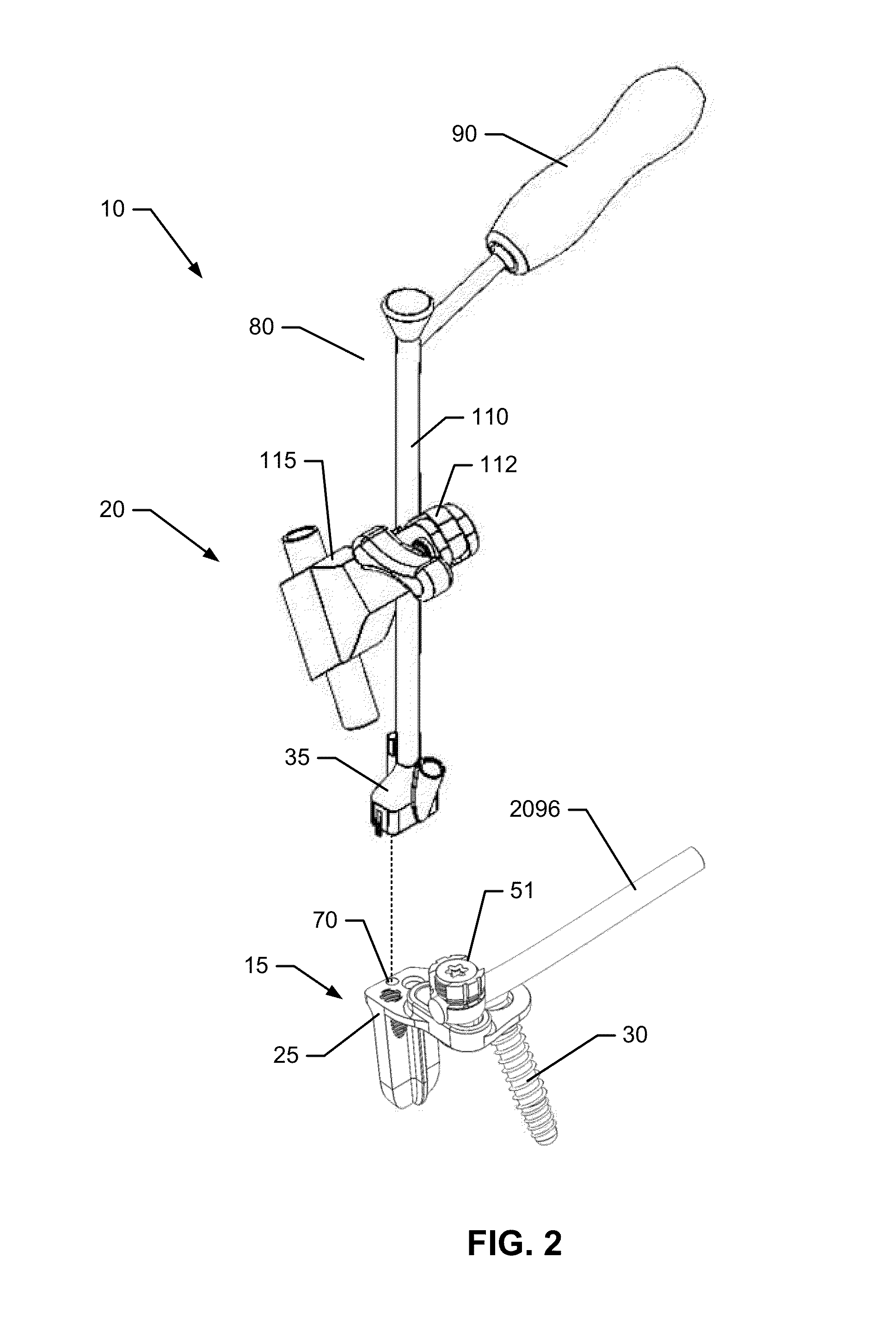
[0159]FIG. 9 is an isometric view of an implant body 25. In this embodiment, an additional lateral attachment bore 75 is provided in the form of an alignment peg receptacle. This alignment peg receptacle 75 may be a blind hole configured to receive an alignment peg protruding from the distal end 35 of the delivery tool 20 (not shown).

[0160]In one embodiment, the center bore 70 may have a diameter ranging from approximately 2 mm to approximately 10 mm. In another embodiment, the one or more lateral attachment bores may each have a diameter ranging from approximately 0.5 mm to approximately 3 mm.

first embodiment

[0161]FIG. 10A is a top view of the implant body 25 illustrated in FIG. 5. In an embodiment, the outer contour 664 of the proximal end 43 of the insertion plate 45 may be contoured to fit within two or more additional alignment pins 150 protruding in a distal direction from the distal end 35 of the delivery tool (not shown). FIG. 10B is the top view of the implant body 25 illustrated in FIG. 10A with the distal end of the delivery tool 20 mounted in place. In this embodiment, the additional alignment pins 150 project in a distal direction to entrap the lateral margin of the proximal end 43. In this configuration, the additional alignment pins 150, in cooperation with a set screw 95 advanced into the central bore 70 of the implant body 25, secure the delivery tool 20 to the implant body 25 and prevent the delivery tool 20 from translating or rotating relative to the implant body 25.

[0162]In an embodiment, the implant body 25 is fixed in place within the joint space of the sacroiliac ...


PUM


Abstract

An orthopedic anchoring system for attaching a spinal stabilization system and concomitantly fusing a sacroiliac joint is disclosed that includes a delivery tool and an implant assembly for insertion into a joint space of a sacroiliac joint. The implant assembly may be secured using anchors inserted through bores within the implant body and into the underlying sacrum and/or ilium. The implant body may also include an attachment fitting reversibly attached to a guide to provide attachment fittings for elements of the spinal stabilization system. The implant assembly may be releasably coupled to an implant arm of the delivery tool such that the implant arm is substantially aligned with the insertion element of the implant assembly. An anchor arm used to insert the anchor may be coupled to the implant arm in a fixed and nonadjustable arrangement such that the anchor is generally aligned with a bore within the implant assembly.

Description

CROSS REFERENCE TO RELATED APPLICATIONS[0001]The present application is a continuation-in-part (CIP) application of U.S. patent application Ser. No. 13 / 236,411, entitled “Systems for and Methods of Fusing a Sacroiliac Joint” filed Sep. 19, 2011, the contents of which are incorporated by reference in its entirety herein. The present application further claims the benefit of and priority to U.S. Provisional Patent Application 61 / 798,225, entitled “Systems and Methods for Fusing a Sacroiliac Joint and Anchoring an Orthopedic Appliance” and filed on Mar. 15, 2013, the contents of which are incorporated by reference in its entirety herein. The present application is also a continuation-in-part (CIP) application of U.S. patent application Ser. No. 13 / 475,695, entitled “Systems for and Methods of Fusing a Sacroiliac Joint” filed May 18, 2012, the contents of which are incorporated by reference in its entirety herein. The present application is also a continuation-in-part (CIP) application ...

Claims


Application Information

Patent Timeline
IPC IPC(8): A61B17/80
CPCA61B17/8066A61B17/025A61B17/1757A61B17/68A61B17/7035A61B17/7043A61B17/7044A61B17/7055A61B17/863A61B17/8645A61B2017/0046A61F2/30988A61F2/4455A61F2/4611A61F2002/30179A61F2002/30622A61F2002/30995A61F2002/4687A61F2310/00017A61F2310/00023A61F2310/00179A61F2310/00359
Inventor DONNER, EDWARD JEFFREYDONNER, CHRISTOPHER THOMAS
Owner JCBD
Why Eureka
Try Eureka