
Liquid injection for scavenging

a liquid injection and exhaust scavenging technology, applied in the direction of machines/engines, mechanical equipment, non-fuel substance addition to fuel, etc., can solve the problems of increasing the catalyst reducing ability, increasing the temperature, increasing the torque, etc., to reduce the knocking tendency, increase the torque, and increase the spark advance

Active Publication Date: 2014-07-24
FORD GLOBAL TECH LLC
View PDF0 Cites 12 Cited by
  • Summary
  • Abstract
  • Description
  • Claims
  • Application Information

AI Technical Summary

Benefits of technology

The patent text discusses a new system and method for reducing emissions in internal combustion engines. The system injects a fluid, like water or windshield washer fluid, directly into the combustion cylinder to flush out hot exhaust products and recharge the cylinder with fresh air. This process, called vapor scavenging, reduces emissions concerns by reducing the amount of residual exhaust gas and the resultant knock tendency, thus allowing greater spark advance which increases torque. Additionally, vapor scavenging can occur even when there is no pressure difference between the intake and exhaust manifolds, which ensures optimal performance under various operating conditions. The method can be used with various fuels and can even be used on engines without timing adjustments. Overall, vapor scavenging is a new and effective way to reduce emissions in engines.

Problems solved by technology

Furthermore, the reduction in the amount of residual exhaust gas leaves more room for fresh air-fuel mixture which further increases torque.
Scavenging is commonly used in the European market, but most turbocharged engines sold in the US market are calibrated to use much less scavenging, due to emissions concerns.
However, traditional scavenging can result in oxygenated fresh air passing through the exhaust valve and on to the exhaust aftertreatment system, resulting in increased emissions.
In particular, increased oxygen lessens catalyst reducing ability thus decreasing the reduction of nitrogen oxides (NOx) prior to venting exhaust gases to the atmosphere.
Furthermore, because the present disclosure relies on the expansion of liquid to vapor to displace the residual exhaust gas, vapor scavenging can occur even when intake manifold pressure is lower than exhaust manifold pressure.

Method used


Image

  • Liquid injection for scavenging
  • Liquid injection for scavenging
  • Liquid injection for scavenging

Examples


Embodiment Construction

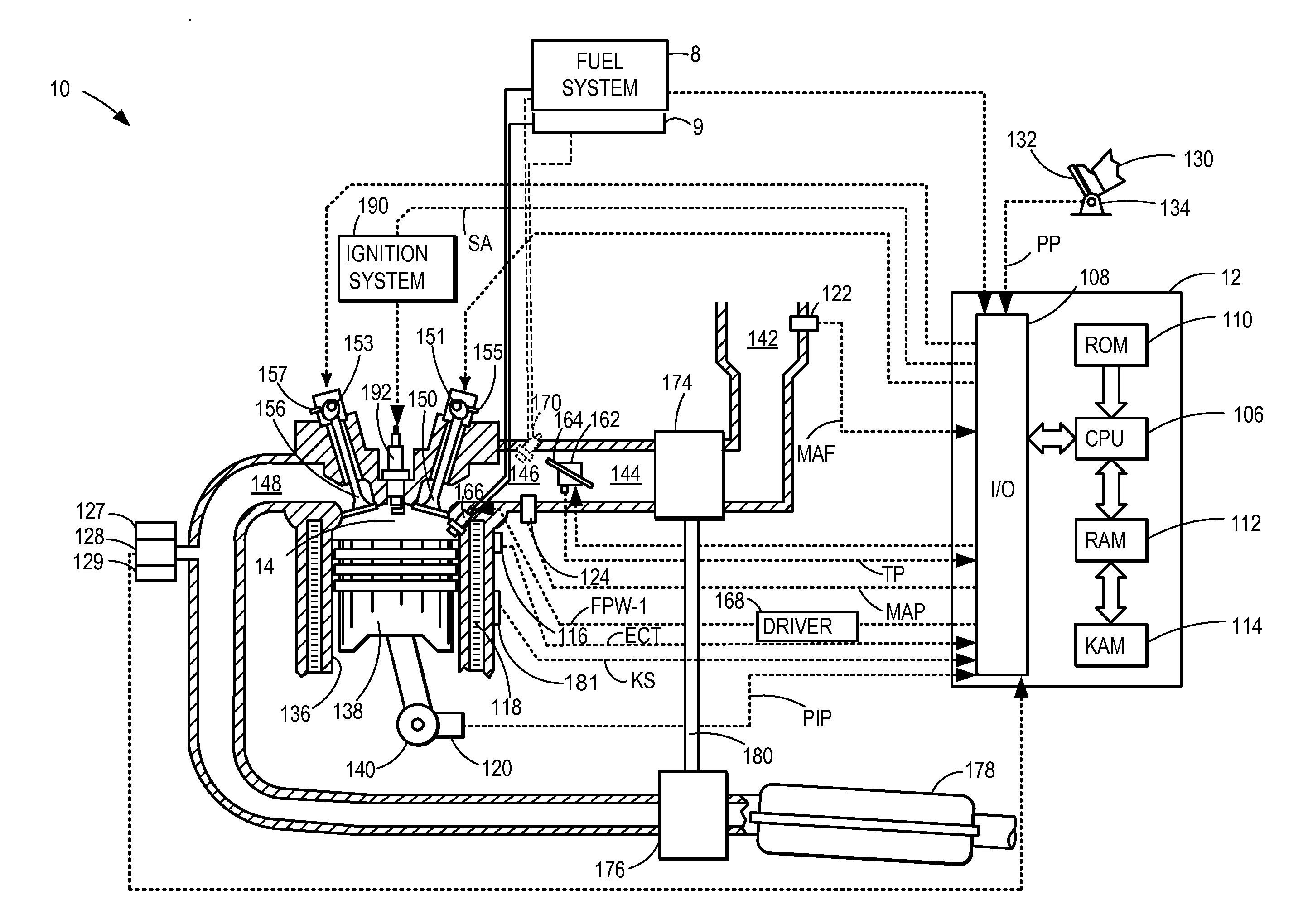
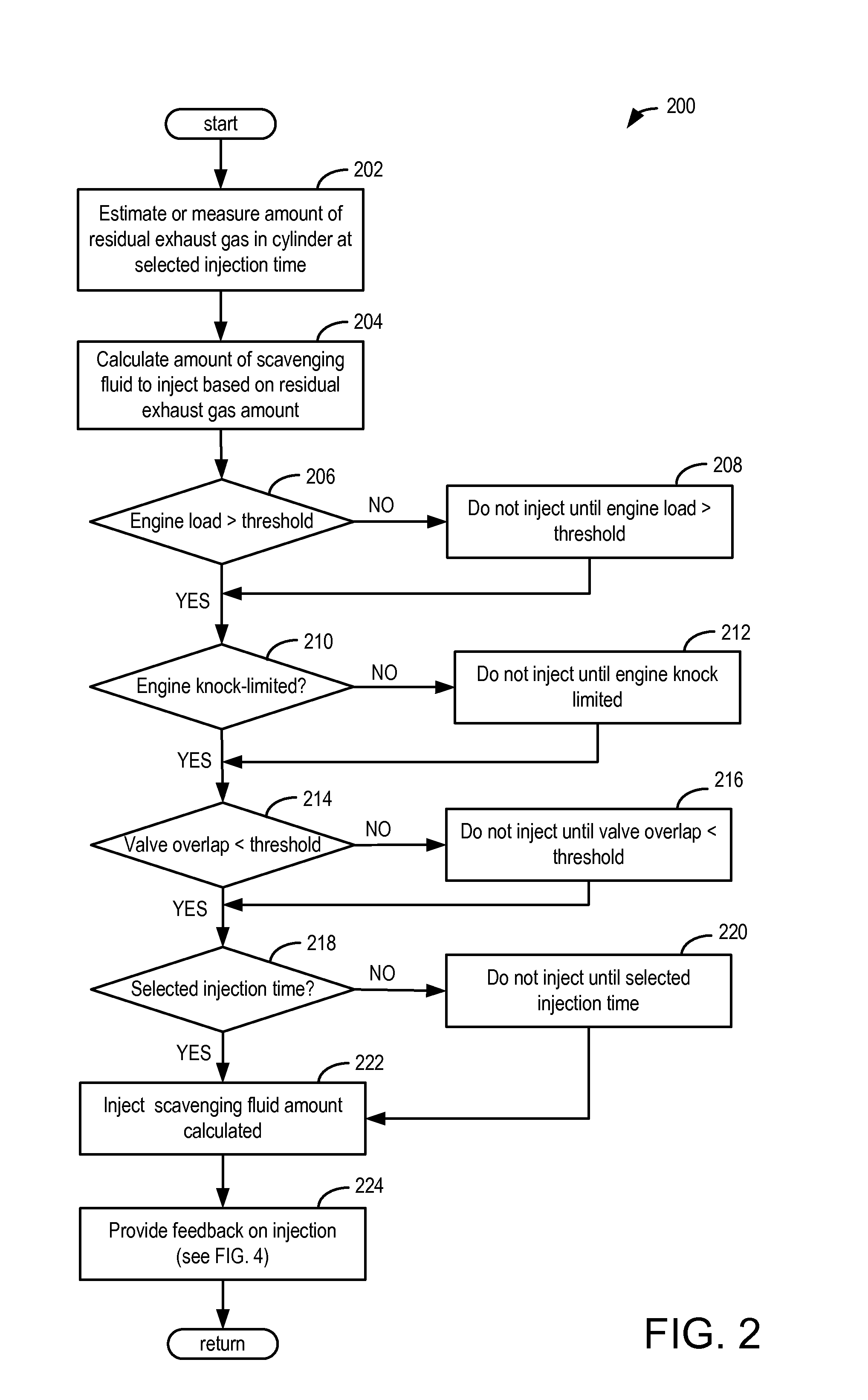
[0013]The present disclosure details injection of a liquid for vapor scavenging. In one embodiment scavenging fluid is direct injected late in the exhaust stroke. In an alternate embodiment, employing port injection, fluid is injected during valve overlap or just before the intake stroke. With port injection into the intake air passage, liquid or vapor is readily taken in through the intake valve where it functions in the same way as directly injected fluid. In both embodiments, liquid is quickly evaporated as it hits hot residual gases or hot surfaces. A small amount of liquid expands as it evaporates and displaces the residual exhaust gas, forcing it past the open exhaust valve or valves. Heat is removed from the hot cylinder both by displacing hot residual exhaust products and through evaporative cooling. In this way, injection of scavenging fluid may also reduce propensity for knock and the method of the present disclosure can be adapted for knock mitigation. Furthermore, the pr...


PUM


Abstract

Methods are provided for controlling an engine. One method may include boosting engine intake air to a cylinder; and injecting an amount of a scavenging fluid into the cylinder based on an amount of cylinder residual exhaust gas. A scavenging fluid, such as water or windshield washer fluid evaporates on contact with the hot exhaust gases and hot metal components and the expanded volume of the vapor displaces the residual exhaust gas, thereby improving engine scavenging.

Description

TECHNICAL FIELD[0001]The present application relates to exhaust scavenging for internal combustion engines.BACKGROUND AND SUMMARY[0002]Exhaust scavenging in internal combustion engines is used to clear hot exhaust products from a combustion cylinder and recharge the cylinder with fresh intake air. Scavenging allows fresh air to flush out most of the residual hot exhaust gas from the clearance volume, and the resulting decrease in temperature reduces knock tendency, thus allowing greater spark advance which increases torque. Furthermore, the reduction in the amount of residual exhaust gas leaves more room for fresh air-fuel mixture which further increases torque. Scavenging is commonly used in the European market, but most turbocharged engines sold in the US market are calibrated to use much less scavenging, due to emissions concerns.[0003]Traditional scavenging, or “blow through”, of fresh air is used when the intake manifold pressure is higher than exhaust manifold pressure. This i...

Claims


Application Information

Patent Timeline
IPC IPC(8): F02B47/08
CPCF02B47/08F02B29/02F02B43/12F02M25/03F02M25/0227F02B47/02Y02T10/12Y02T10/30
Inventor LEONE, THOMAS G.ULREY, JOSEPH NORMAN
Owner FORD GLOBAL TECH LLC
Learn More