
Method of Reducing Corrosion on Metal Surfaces

a metal surface and corrosion technology, applied in the direction of drilling rods, drilling pipes, drilling holes/well accessories, etc., can solve the problems of limited rotation of jointed pipes and movement along the wellbore, inability to further drill, and limited effect of beads in coil tubing and workover applications inside the casing

Inactive Publication Date: 2014-07-24
NOLES INTPROP
View PDF4 Cites 0 Cited by
  • Summary
  • Abstract
  • Description
  • Claims
  • Application Information

AI Technical Summary

Benefits of technology

The patent text describes a method of protecting metal surfaces from corrosion during chemical additive treatments in oil and water mixtures. The method involves adding polymer particles, such as polytetrafluoroethylene, along with a suspending agent and surfactant to the oil. This mixture is then applied to the metal surface to reduce corrosion. The technical effect is improved protection against corrosion during well drilling and completion operations.

Problems solved by technology

The friction between the coiled tubing or jointed pipe and the casing in the horizontal section of the well may become equal to the force available to move the coiled tubing or pipe along the horizontal section, at which point further drilling is not possible.
But, even with jointed pipe in wells where the wellbore has been drilled with directional changes, causing “doglegs” or a crooked wellbore, the rotation of jointed pipe and movement along the wellbore may be limited.
The effectiveness of these beads in coil tubing and workover applications inside the casing has been limited.

Method used


Image

  • Method of Reducing Corrosion on Metal Surfaces
  • Method of Reducing Corrosion on Metal Surfaces
  • Method of Reducing Corrosion on Metal Surfaces

Examples


example 1

[0022]A 200 gram sample was prepared by mixing a 0.5% solution of the composition given in Table 1 into distilled water and mixing in a 200 mL beaker with magnetic stirring for 3 minutes.

TABLE 1Hydrocarbon oil91.2%by wt.Ethylene bis-amide5%by wt.Polyethylene Glycol 600 dioleate tallate2%by wt.TEFLON Particles1.8%by wt.

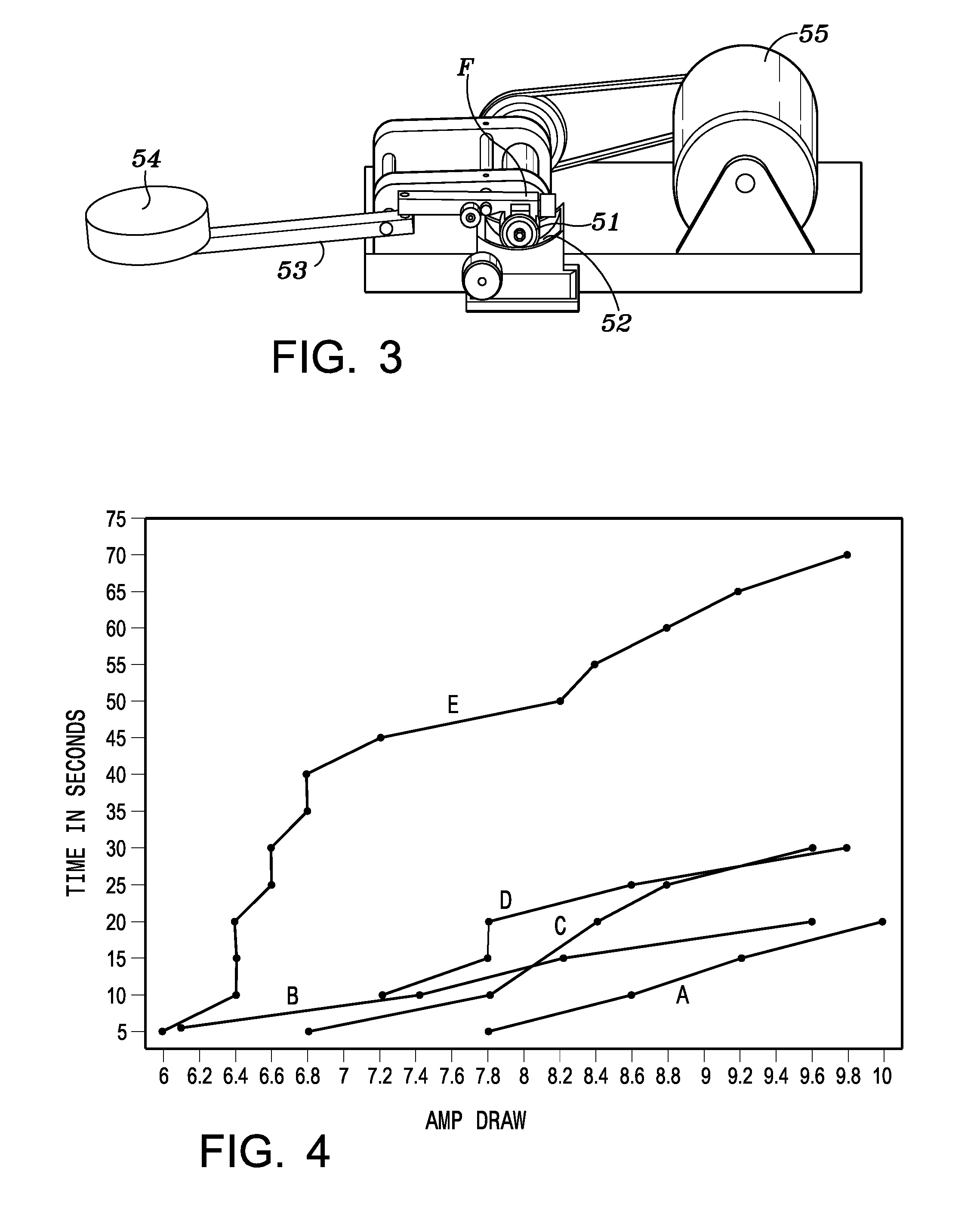
[0023]The sample was then quickly poured into cup 52 (FIG. 3). While holding the weight off the static bearing surface, the unit was turned on to allow the solution to coat the bearing surface. After a brief time, arm 53 was lowered to apply a force of 200 pounds on the bearing surfaces and the timer was started. After completion of a test, the cup was removed from the tester and cleaned with isopropyl alcohol. The bearing surfaces were removed and replaced with new ones. Tests were performed with the mixture of Example 1 and with other fluids.

[0024]FIG. 4 is a graph showing the amperage drawn by the motor over a period of time with different fluids in the test apparat...

example 2

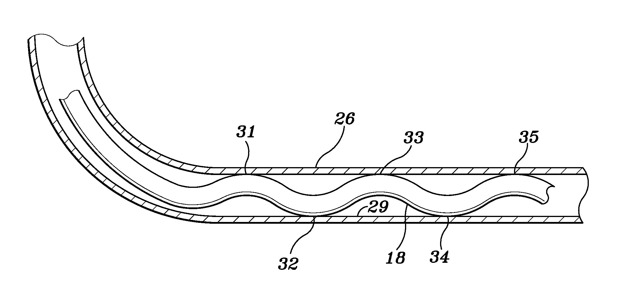
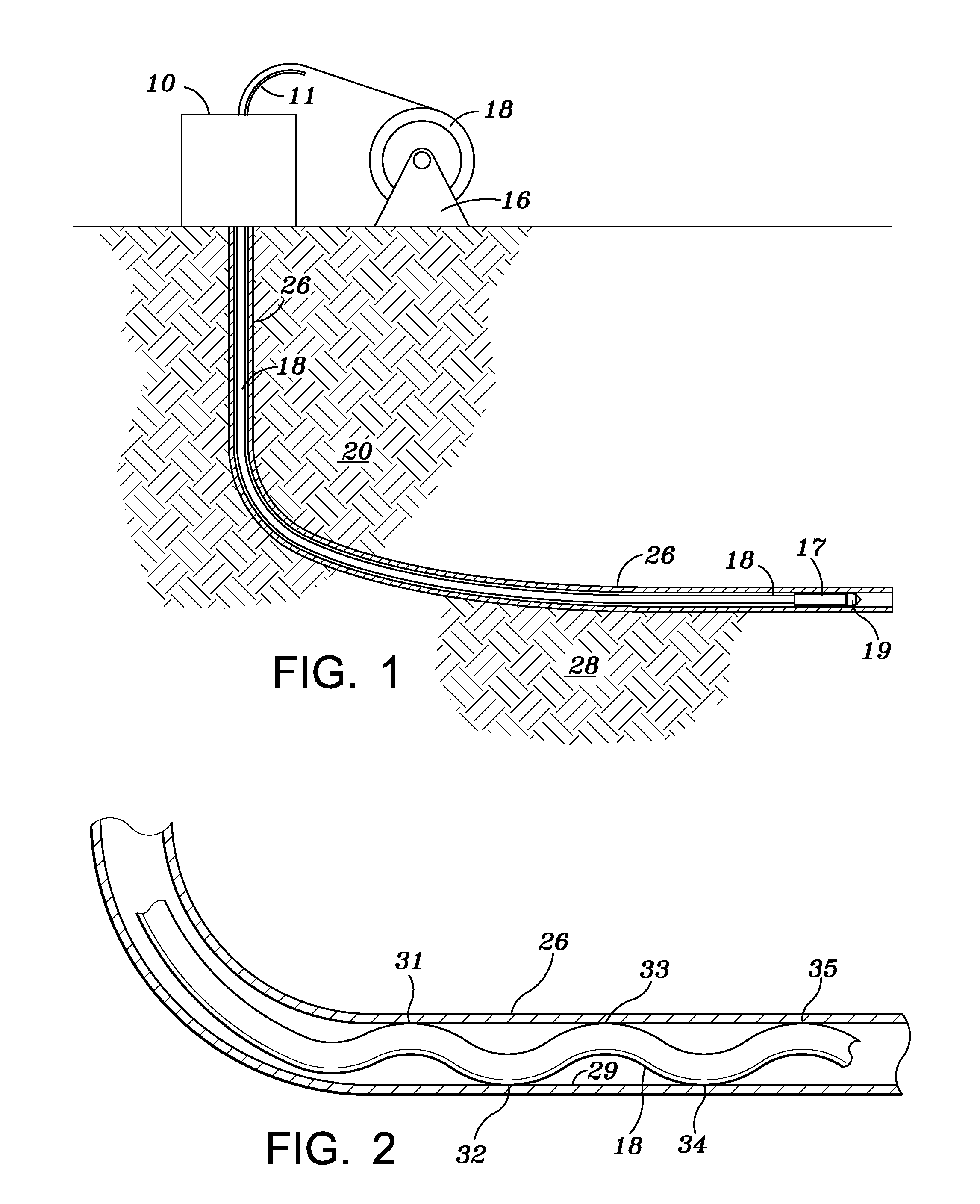
[0026]A well operator had set 10 bridge plugs inside casing in the horizontal section of a well in Texas. Operations to drill the bridge plugs were conducted using coiled tubing. The well had a vertical depth of about 8,290 ft and had a measured depth of about 13,220 ft. Coiled tubing had been used to drill all plugs but the bottom two plugs. Using a prior art friction reducing fluid, friction limited the ability to drill the last two plugs. The decision was made to try the oil phase composition disclosed herein. After adding the oil phase mixture disclosed in Example 1 to water at rates of 1 or 2 gals per 10 bbls and circulating the present fluid up the annulus outside the coiled tubing, the final two plugs were reached and drilled. In a second well drilled from the same pad as the first well, friction was higher than in the first, but all the plugs were successfully drilled from the well using the composition disclosed herein. The representative of the well operator who was presen...


PUM

PropertyMeasurementUnit
concentrationaaaaaaaaaa

Abstract

A method for reducing corrosion on the exterior or interior surface, for example coiled tubing and casing, is disclosed. The method includes mixing a selected surfactant and particles of a polymer in oil, then adding the oil to water and contacting the surfaces of the tubing with the mixture.

Description

[0001]This application is a divisional application of a U.S. application Ser. No. 13 / 075,465 filed Mar. 30, 2011.BACKGROUND OF INVENTION[0002]1. Field of the Invention[0003]This invention is directed to a method for reducing corrosion on metal surface. More particularly, a mixture of polymer particles in an oil phase are added to a water-based fluid such that the particles are transported to an oil film on the metal surface. The materials disclosed reduce the amount of corrosion on surfaces of tubulars.[0004]2. Description of Related Art[0005]In recent history the oil and gas industry has discovered that drilling horizontally within an oil and gas reservoir can potentially make a much more productive well. The horizontal well allows access to much larger volumes of the oil- and gas-bearing formation. The longer the lateral or horizontal section the more productive the well can be. For this reason, it has become increasingly common to drill horizontally in many oil and gas formations...

Claims


Application Information

Patent Timeline
Patent Type & Authority Applications(United States)
IPC IPC(8): E21B41/02
CPCE21B41/02E21B29/00C09K8/54C09K2208/32C09K8/588C09K8/28C09K2208/28C09K8/03E21B17/20E21B21/062
Inventor NOLES, JR., JERRY W.WATTS, ALEX J.
Owner NOLES INTPROP
Learn More