Method and Device for the Mechanical or Mechanical-Biological Treatment of Waste

a technology of mechanical or mechanical-biological treatment and waste, which is applied in the direction of grain treatment, waste based fuel, fuel, etc., can solve the problems of high technical cost, large area and time consumption during the final rotting of such waste, and high water consumption, so as to reduce water content and water content. the effect of long residence time and reducing water conten

Active Publication Date: 2014-07-24
ZWECKVERBAND ABFALLBEHANDLUNG KAHLENBERG
View PDF8 Cites 5 Cited by
  • Summary
  • Abstract
  • Description
  • Claims
  • Application Information

AI Technical Summary

Benefits of technology

[0051]By way of the method according to the invention, during the intermixing and homogenization, water is only removed from the process when the waste has too high a water content. As a result, a long residence time of the water in the process is achieved and the water throughput overall is lowered. Furthermore, a high organic component remains in the waste, such that the substitute fuel subsequently produced therefrom has a high biogenic component. If waste having a lower water content than the waste currently located in the container is also available, the water content can also be lowered overall by the introduction of this drier waste. Since only little water is removed from the process, only a small amount of water has to be reprocessed, too. Appropriate downstream units are required only little and can be given smaller dimensions.
[0052]As a result of the provision of a plurality of input points in the various zones of the waste treatment plant embodied preferably as a multi-zone reactor, it is furthermore possible to regulate the treatment time of the waste. Thus, for example homogeneous fibrous or sludge-like waste, which requires only a short residence time in the waste treatment plant, can be introduced into the waste treatment plant at an input point located close to an output point. As a result, the effective processing capacity of the waste treatment plant can be optimized.
[0053]Furthermore, in the method according to the invention, no or only a little biological activity in the waste is desired. This avoids the situation in which, in order to maintain aerobic processes, large quantities of oxygen-rich air have to be introduced into the waste. In the method according to the invention, only air or inert gas is fed in order to prevent the formation of explosive atmospheres. A further effect of this is that a smaller quantity of waste air has to be processed in order to avoid undesired emissions and odour nuisance in the environment of the waste treatment plant.
[0054]The provided breaking up of clumps and / or caking prevents roll-shaped material accumulations that otherwise occur and would rotate together with the agitator arms. The breaking up of these material accumulations at an early stage ensures improved homogenization of the waste and guarantees a constant quality of the substitute fuel obtained.
[0055]The preferred introduction of water into the regions which have been loosened by the agitator arms or by the breaking up of clumps ensures that the water can penetrate easily and fully into the material. The contact between waste and water is considerably improved and the removal of harmful substances from the waste is made easier.
[0056]As a result of the selective comminution of the biomass contained in the waste by the agitator, the organic constituents can be distributed uniformly throughout the material during homogenization. At the same time, the coarse structures of the material are retained. The coarse material structures ensure that the material can be aerated well during downstream biological drying. As a result, a uniform drying result and constant quality of the substitute fuel obtained from the material is ensured.
[0057]On account of the introduced waste being transported by means of equalization of the filling level, additional advancing elements, for example on the agitator, are superfluous. As a result, not only can the agitator be optimized fully for its homogenization and comminution function, but also the transport of the waste becomes independent of the direction of rotation of the agitator. This makes it possible to reverse the direction of rotation of the agitator multiple times during the intermixing of the material. In this way, wear on one side is prevented and wrapping with elongate waste parts such as strings, cables, sheets and the like is minimized.
[0058]As a result of the provided optical examination of the interior of the reactor container, it is not only easy to draw conclusions about the material consistency, but also possible critical system states can be easily detected and remedied.
[0059]Since, in the method according to the invention, aerobic decomposition and / or aerobic hydrolysis do not have to be actively supported, it is not necessary to introduce oxygen-rich air into the waste. It is therefore possible to dispense with the arrangement of corresponding systems, for example air lances. Similarly, the much lower removal of water from the process has an advantageous effect on the means for removing water. These can now generally be covered with a slide so that no material can penetrate into them. Clogging of the means for removal of water is therefore unlikely and the arrangement of corresponding means for scraping free or flushing the means for removal of water is superfluous.
[0060]The provision of a pressure-resistant slide at the at least one output point guarantees reliable operation of the plant even in the case of operating errors or of critical operating states brought about by the input of particularly water-rich waste. Waste or free water located in the waste treatment plant can be retained reliably until the material consistency has been set back to a value which ensures reliable and controlled removal,

Problems solved by technology

The biomass to be decomposed is thus not reutilized further and the area and time consumption during the final rotting of such waste is comparatively large.
A disadvantage of this method is a comparatively large water consumption, wherein the water outlets are easily clogged by penetrating waste, this requiring high technical outlay for cleaning and keeping the outlets clear.
It has also been shown that, as a result of intensive aeration of the waste, aerobic hydrolysis is not substantially promoted and is not essential for the process.

Method used


Image

  • Method and Device for the Mechanical or Mechanical-Biological Treatment of Waste
  • Method and Device for the Mechanical or Mechanical-Biological Treatment of Waste
  • Method and Device for the Mechanical or Mechanical-Biological Treatment of Waste

Examples


Embodiment Construction

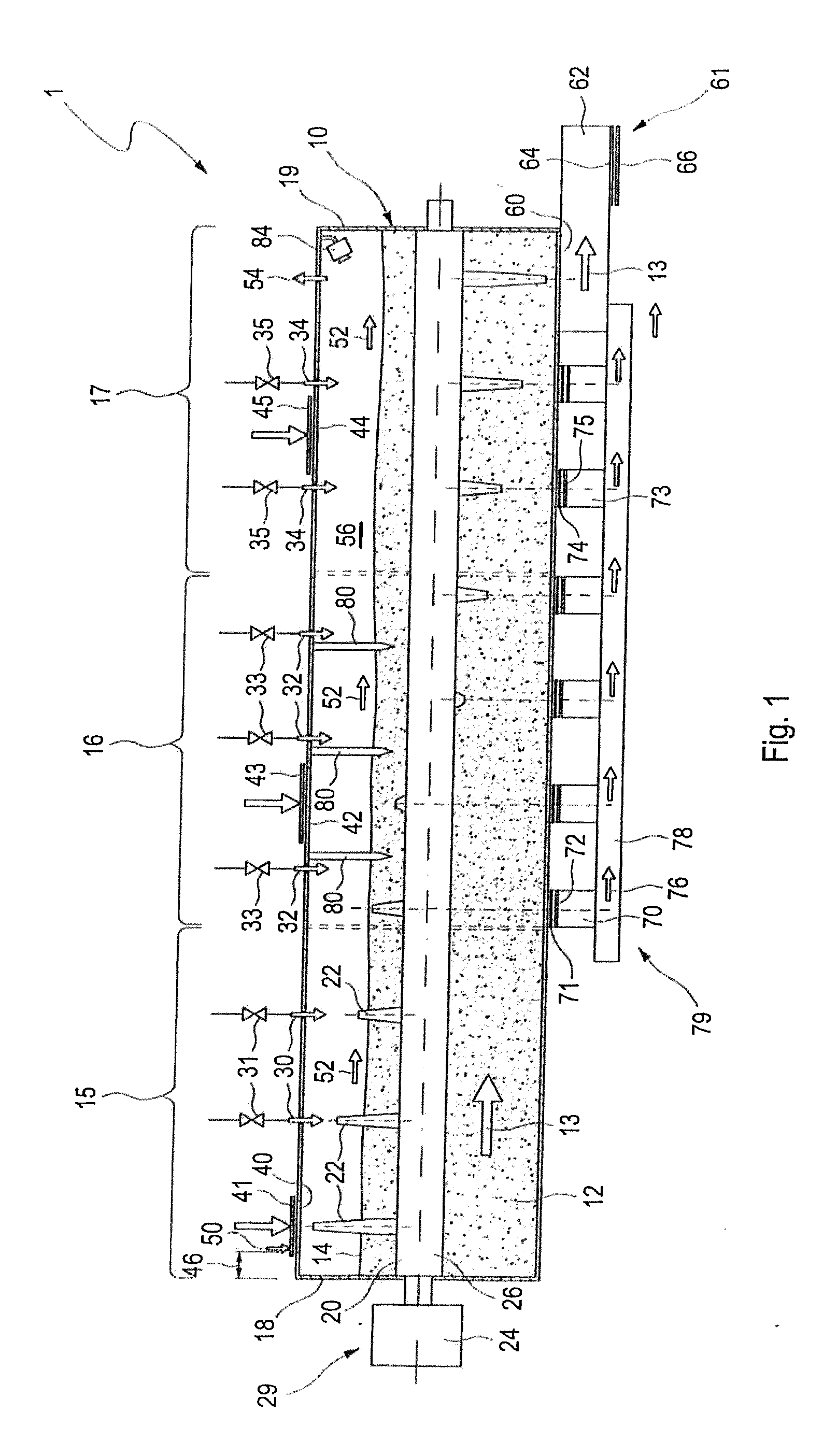
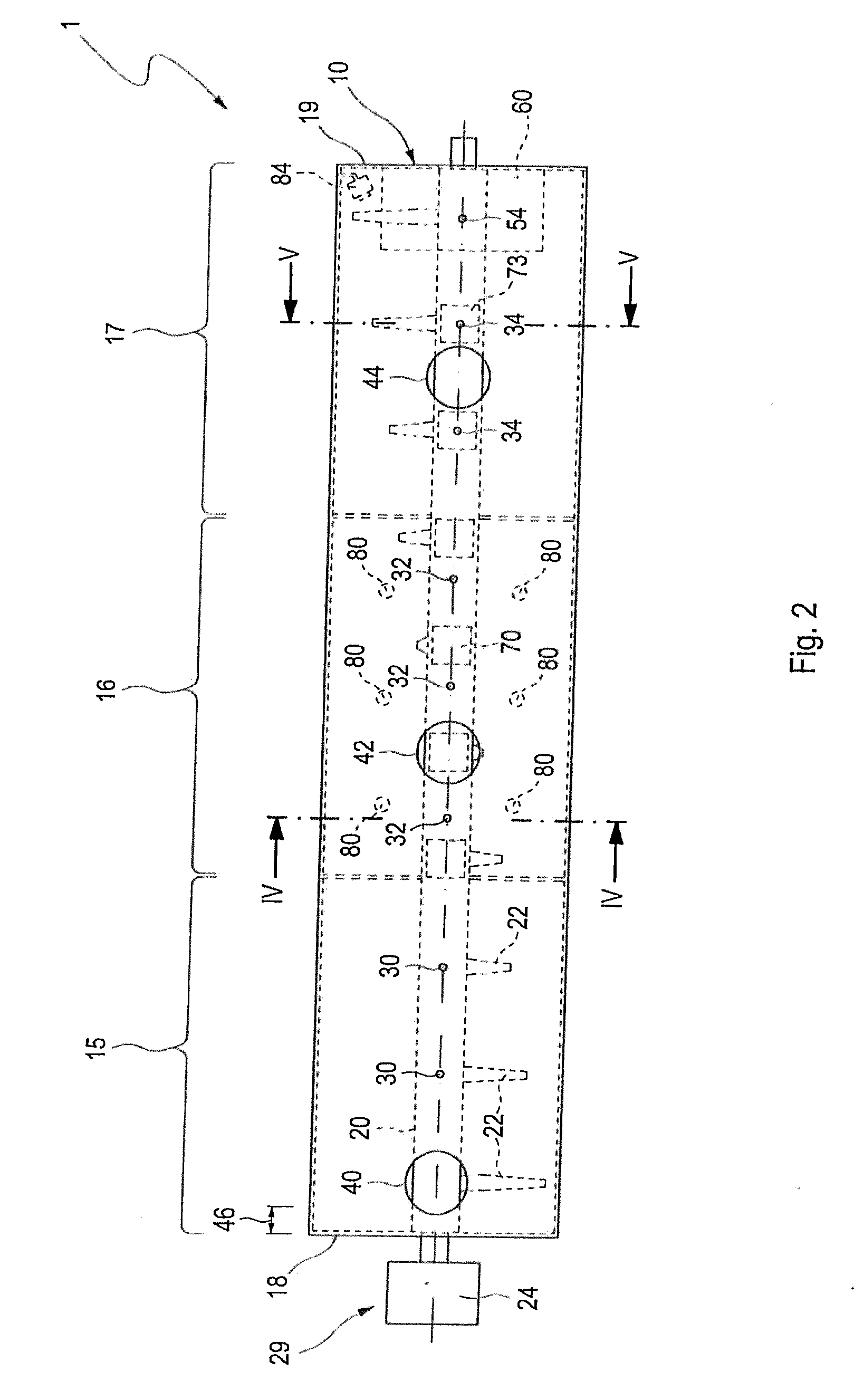
[0068]FIG. 1 shows a schematic illustration of the waste treatment plant according to the invention in an illustration from the side.

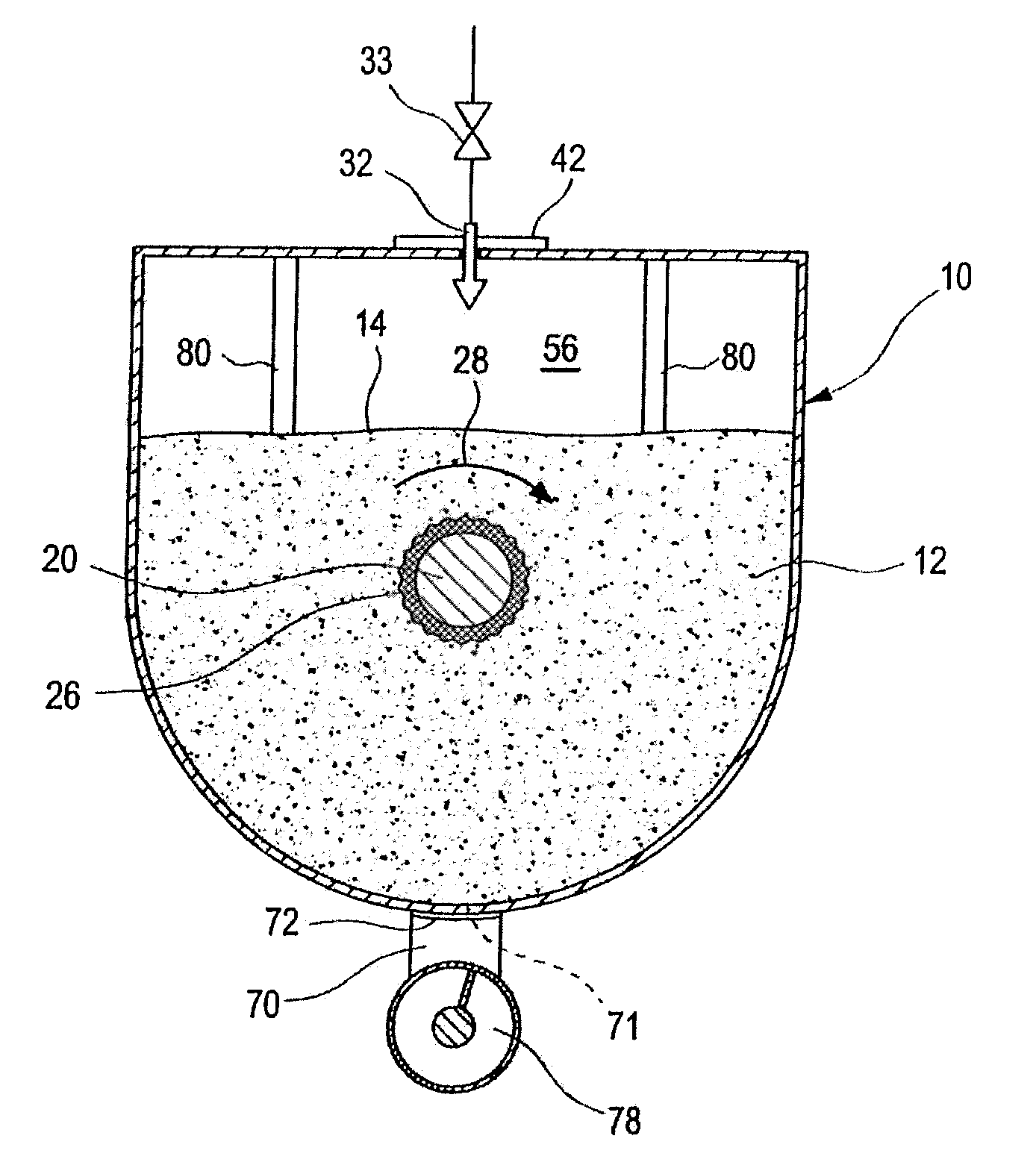
[0069]FIG. 1 shows a reactor container 10, which is embodied as a horizontal container. The length of the reactor container 10 is typically in the range from 20 m to 30 m. In the lower region, the cross section of the reactor container is preferably round, in particular embodied as a circular area. The diameter of the container 10 is between 3 m and 6 m. In the upper region, in addition to rounded geometries, angular, for example rectangular geometries, are also possible. Examples are given in the subsequent views from the front. The reactor container 10 accommodates an agitator shaft 20 which passes through the reactor container 10 along the entire length from the front end wall 18 to the rear wall 19. In the embodiment illustrated in FIG. 1, the agitator shaft 20 breaches the end wall 18 and the rear wall 19. On the side of the end wall 18, an agitat...


PUM

PropertyMeasurementUnit
lengthaaaaaaaaaa
diameteraaaaaaaaaa
diameteraaaaaaaaaa

Abstract

The invention relates to a method for treating waste in a mechanical or mechanical-biological waste treatment plant, comprising the following steps of:introducing waste-into the waste treatment plant at least one input point,homogenizing the waste by way of at least one agitator,determining the consistency of the waste in the waste treatment plant,adding water or waste which has a higher water content than the waste in the waste treatment plant in a first scenario, or removal of water or addition of waste having a lower water content in another scenario,transporting the introduced waste to at least one output point,removing the waste. The waste treatment plant is subdivided into at least two zones and in each zone the consistency of the waste is regulated separately by the input of waste and / or addition or removal of water.

Description

[0001]The invention relates to a method for the treatment of waste in a mechanical or mechanical-biological waste treatment plant, and to a device for the mechanical or mechanical-biological treatment of waste.PRIOR ART[0002]Since 2005 in Germany, it has only been possible to deposit waste, in particular municipal waste and domestic waste, at a landfill when it has been pretreated. The assignment criteria with which the pretreated waste has to comply are defined in the German landfill ordinance (Deponieverordnung, DepV). Essentially, the biogenic component and the combustible constituents in the waste in question have to be reduced considerably in order that the assignment values for landfilling can be met. The reduction of these constituents in the waste to be landfilled and also the reduction to a minimum of the waste to be landfilled by recycling and reutilization is increasingly gaining in importance in the EU on account of EU-wide regulations.[0003]If waste is thermally treated...

Claims


Application Information

Patent Timeline
Patent Type & Authority Applications(United States)
IPC IPC(8): C10L5/40B02C23/02
CPCB02C23/02C10L5/40Y02E50/10C10L5/46C10L5/48B02C18/0092B02C18/0084B02C17/1815Y02E50/30
Inventor GIBIS, GEORGPERSON, GEORG
Owner ZWECKVERBAND ABFALLBEHANDLUNG KAHLENBERG
Why Eureka
Try Eureka