
Gas analyzer, respirator or anesthesia device with operating guide

a gas analyzer and operating guide technology, applied in the field of electrical and medical engineering, can solve the problems of user not receiving any information, user cannot possibly operate and/or control the device, and is usually time-consuming, so as to ensure efficient and error-free fast and efficient operation of the device, and the effect of fast and efficient operation

Active Publication Date: 2014-07-24
DRAGERWERK AG
View PDF21 Cites 4 Cited by
  • Summary
  • Abstract
  • Description
  • Claims
  • Application Information

AI Technical Summary

Benefits of technology

The present invention provides an operating guide for medical devices such as respirators and anesthesia devices. The guide allows users to quickly and efficiently operate the device by providing position data and other information on the operational controls. The guide can also provide a chronology of device operating actions or a sequence of handling steps to users. Additionally, the invention includes a help function that displays necessary information to users and a selection signal that directs users to the operational control. The technical effects of the invention include better operational control of medical devices and improved user efficiency in performing medical procedures.

Problems solved by technology

A problem in the previous devices according to the state of the art can be seen in that a user cannot possibly operate and / or control the device without error and appropriately when he does not have sufficient knowledge about the device and corresponding practical experiences in the operation of the device.
In complicated medical devices, it has proven to be a drawback in the state of the art that the user has to move through text information of the help menu, which is usually time-consuming.
Another drawback of the above-mentioned prior-art process can be seen in that the user does not receive any information about the respective position or arrangement of the operational control to be operated at the device.

Method used


Image

  • Gas analyzer, respirator or anesthesia device with operating guide
  • Gas analyzer, respirator or anesthesia device with operating guide
  • Gas analyzer, respirator or anesthesia device with operating guide

Examples


Embodiment Construction

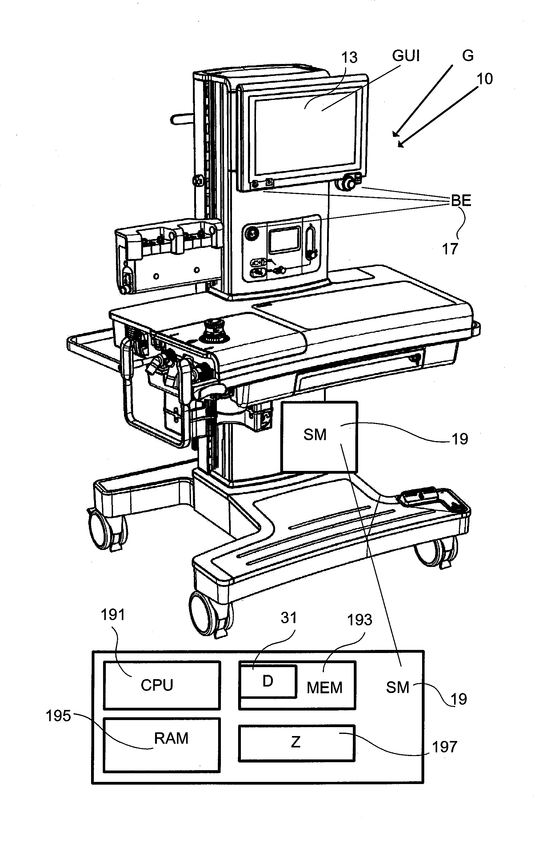
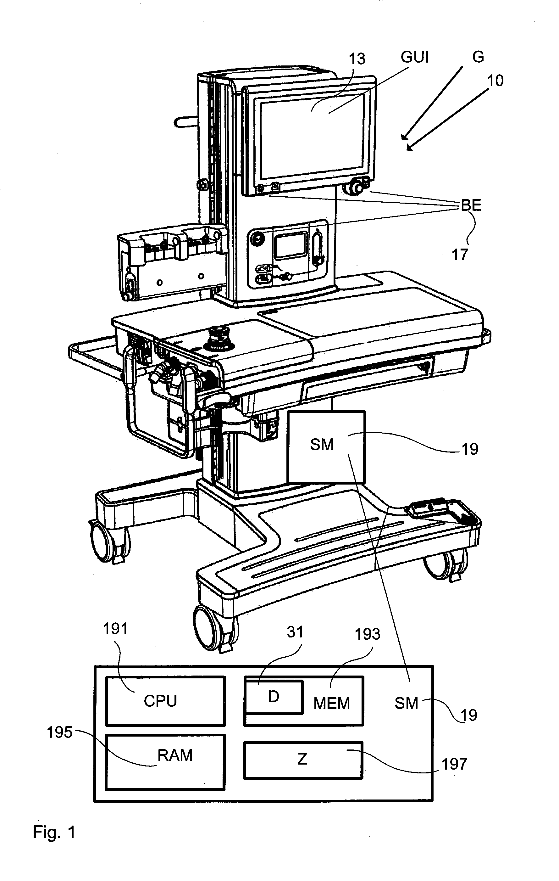
[0060]Referring to the drawings in particular, the present invention is explained in detail below with reference to FIG. 1.

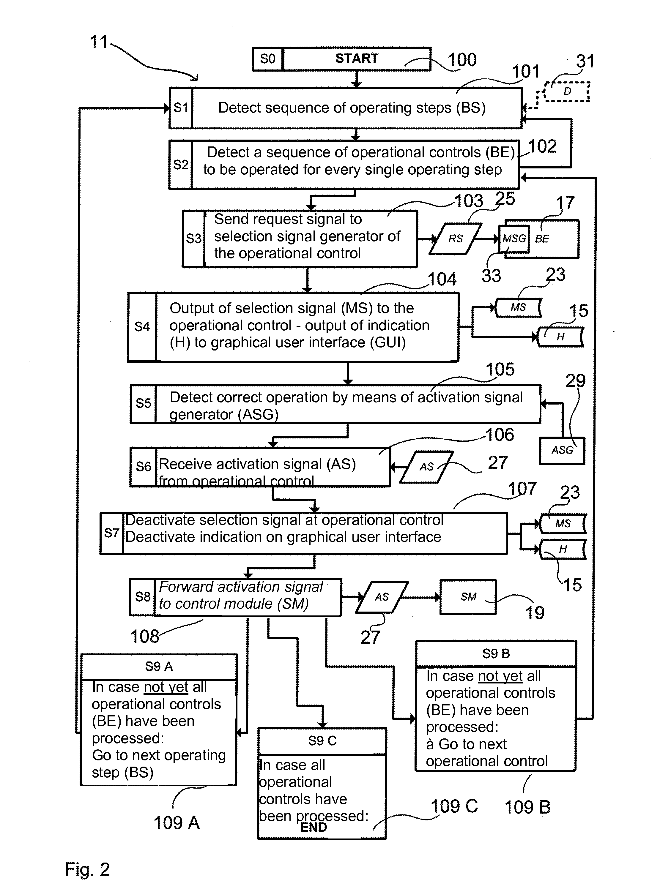
[0061]The present invention pertains to a possibility for controlling a gas analyzer, respirator or anesthesia device, whereby an anesthesia device as device G, 10 is shown as an example in this FIG. 1. The present invention may, however, be pertinent not only to gas analyzers, respirators or anesthesia devices, but also to emergency respirators, lung monitoring systems, drug measuring devices, gas measuring systems or other medical devices, which have a graphical user interface GUI, 13 and operational controls BE, 17. A sequence of operating steps BS, 11 (FIG. 2) is usually executed on the medical device. The present invention is used for a guided or interactive execution of the required sequence of operating steps BS, 11 (FIG. 2), whereby the user shall be guided from step to step. In this case, usually always one operating step requires at least partially an ...


PUM


Abstract

A process for the control of a gas analyzer, respirator or anesthesia device (10), a control module (19) and a gas analyzer, respirator or anesthesia device (10) are provided with a control module (19). The process is used for the output of online help and for guiding the user via a sequence of operating steps that are executed via defined operational controls (17). Each operational control (17) is designed with a selection signal generator and with an activation signal sensor in order to make possible a visual selection of the respective operational control. The selection may be coupled with the output of a visual indication on the graphical user interface (13).

Description

CROSS REFERENCE TO RELATED APPLICATIONS[0001]This application claims the benefit of priority under 35 U.S.C. §119 of German Patent Application DE 10 2013 001 181.7 filed Jan. 24, 2013, the entire contents of which are incorporated herein by reference.FIELD OF THE INVENTION[0002]The present invention lies within the fields of electronics and medical engineering and pertains, in particular, to gas analyzers, respirators or anesthesia devices and the operation thereof.BACKGROUND OF THE INVENTION[0003]A gas analyzer, respirator or anesthesia device or other devices in the field of respiration technology and intensive medicine technology, as well as physiological monitoring usually comprise a plurality of functional components, such that the operation and control of the medical device is not a trivial task, especially since frequent, life-preserving procedures for the patient are connected with it. An anesthesia device or respirator, for example, is usually able to perform different devi...

Claims


Application Information

Patent Timeline
IPC IPC(8): A61B5/00A61M16/00A61M16/01A61B5/08
CPCA61B5/082A61B5/7405A61B5/742A61B5/7475A61M16/0051A61M2205/587A61M16/01A61M16/00A61M2205/505A61M2205/581A61M16/0057A61B5/08A61B5/7435A61M16/024G16H40/63
Inventor GERDER-KALLISCH, ULRIKE
Owner DRAGERWERK AG
Learn More