Eureka AIR delivers breakthrough ideas for toughest innovation challenges, trusted by R&D personnel around the world.

Device for laser thermal ablation with centering means and equipment comprising said device

a laser and thermal ablation technology, applied in the field of laser thermal ablation systems, can solve the problems of reducing the section for passing coolant, and achieve the effects of reducing the negative effect of the spacer, and improving the operation of the devi

Active Publication Date: 2019-10-24
ELESTA
View PDF0 Cites 0 Cited by
  • Summary
  • Abstract
  • Description
  • Claims
  • Application Information

AI Technical Summary

Benefits of technology

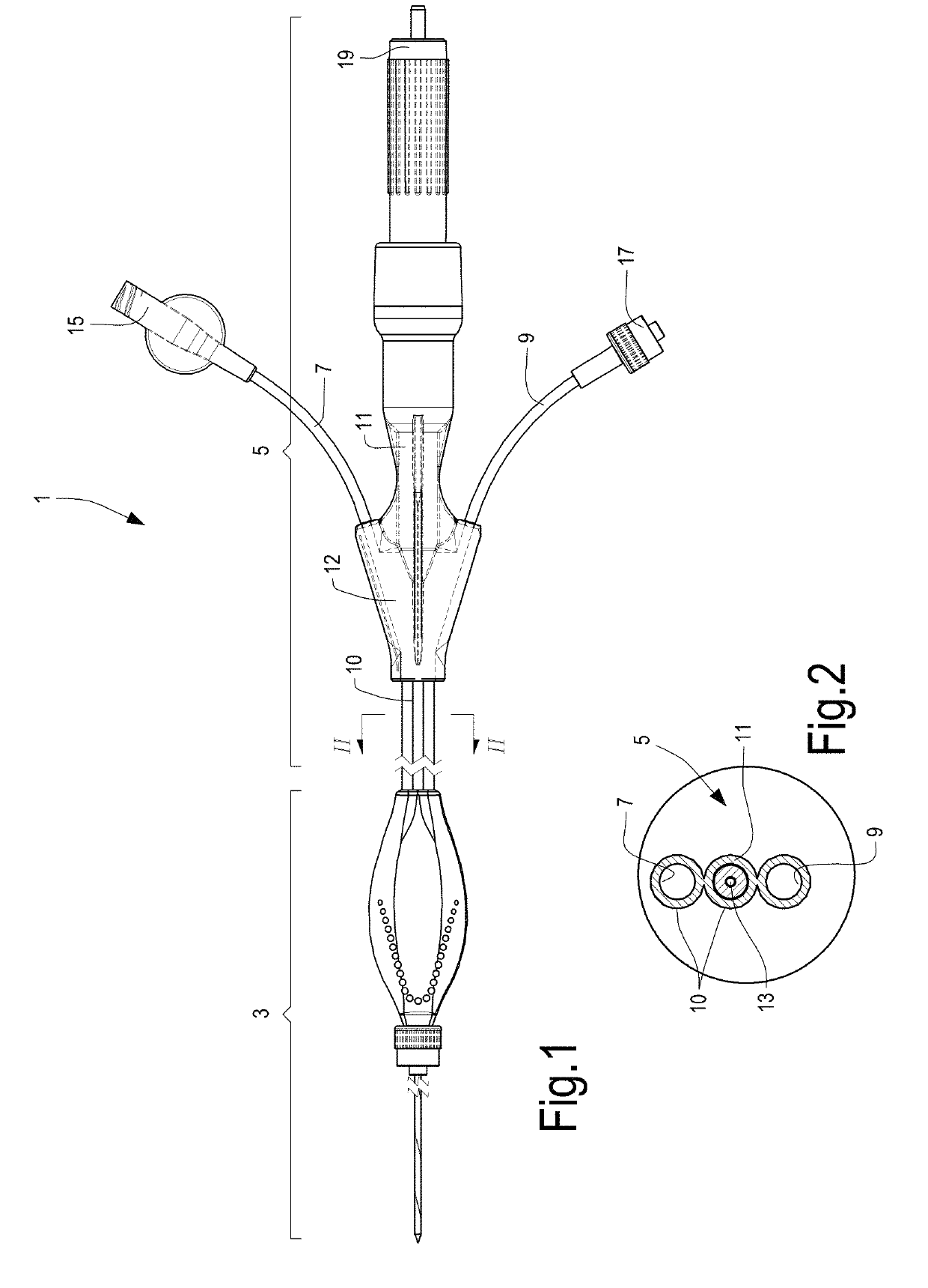
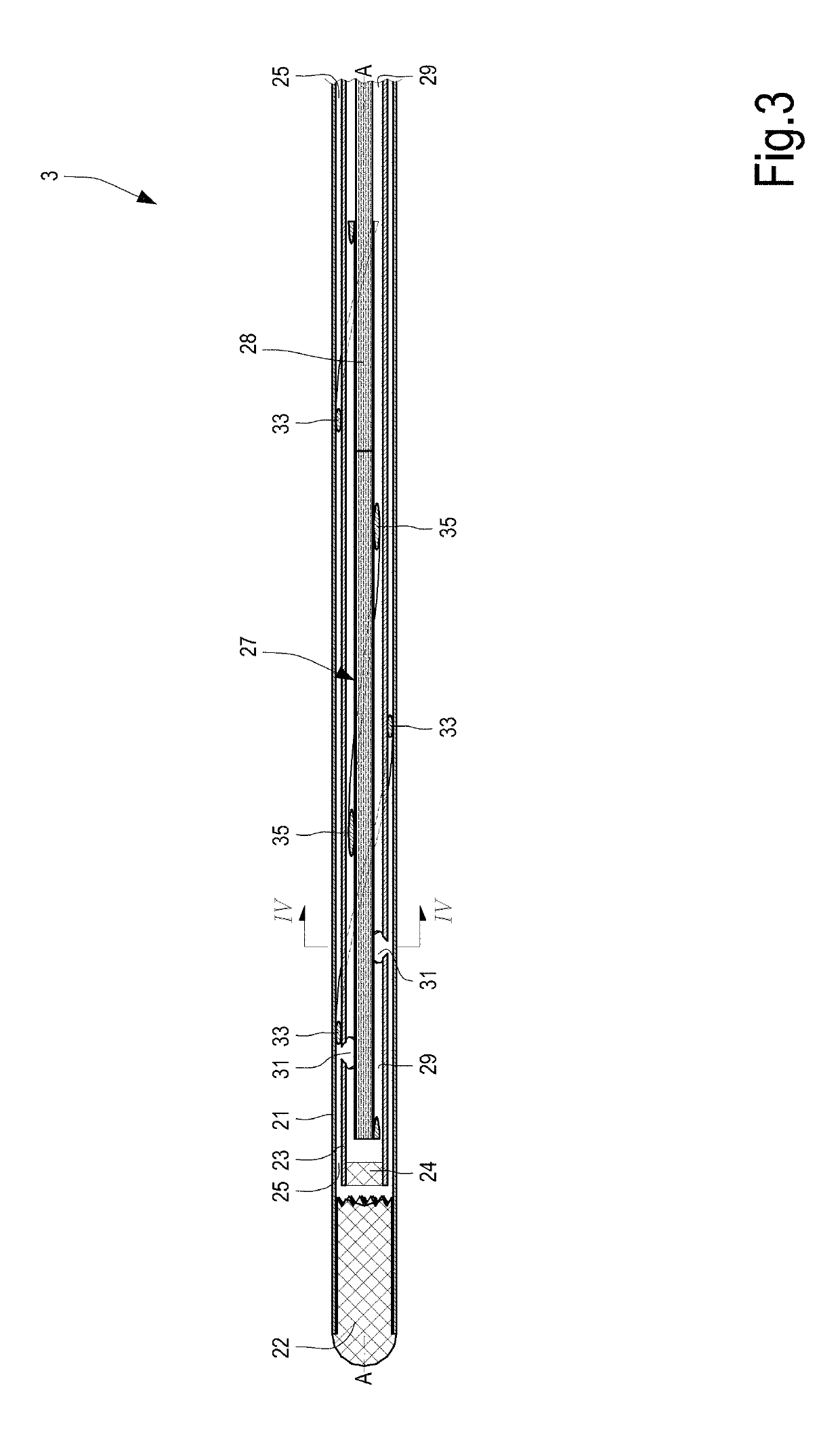
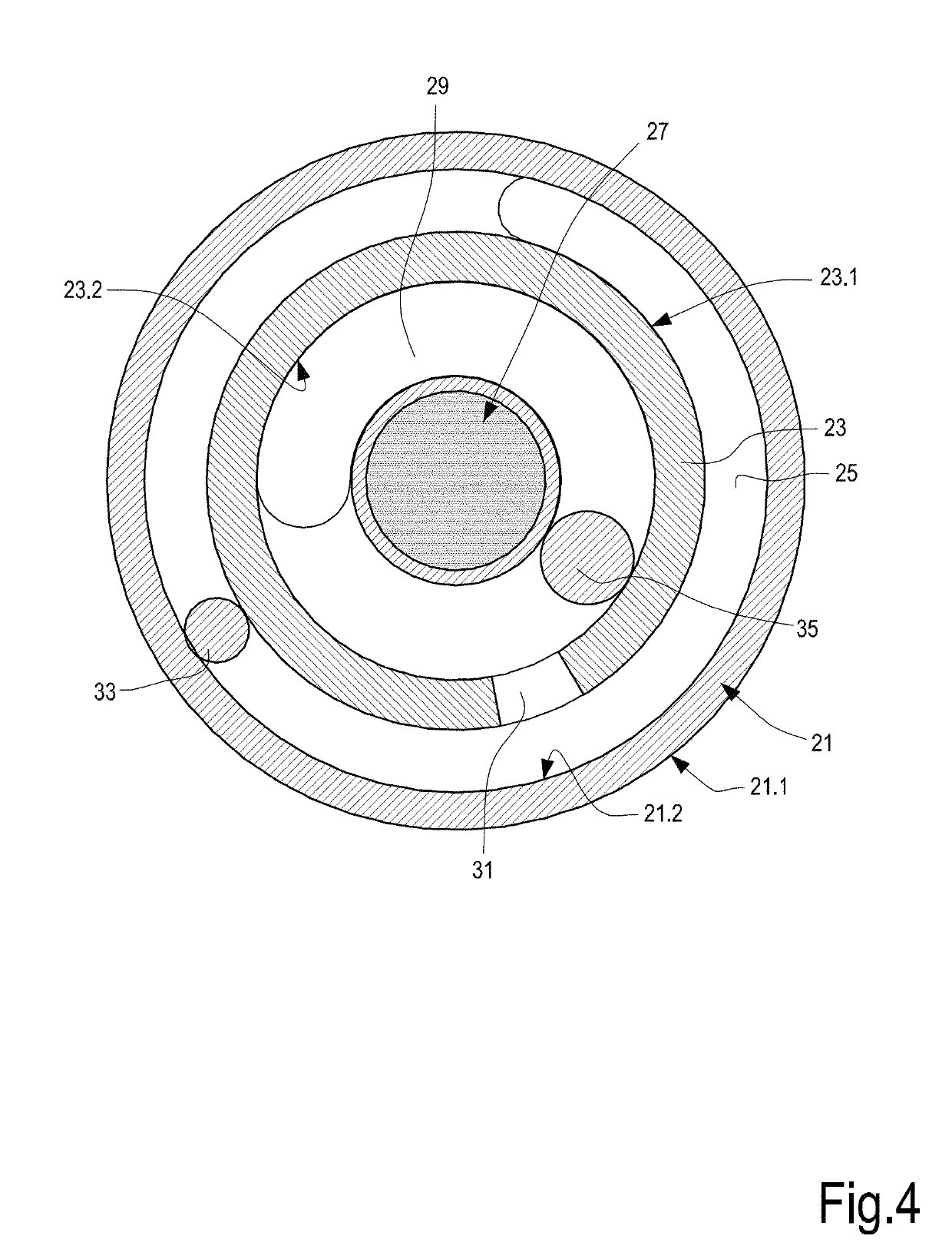
This patent describes a device for laser thermal ablation which has improved performance in providing uniform laser radiation. The device includes an outer tubular structure and an inner tubular structure with a gap between them. To address the negative effect of conventional straight spacers on the coolant flow, a first helical spacer is positioned between the outer tubular structure and the inner tubular structure. This first helical spacer is designed to minimize the impact on the coolant flow and maximize the advantage in terms of ensuring concentricity and coaxiality. In addition, a second helical spacer may be used to further reduce the negative incidence of the spacer on the coolant flow. The device also has a core and a sheath made of materials that are transparent to the wavelength of electromagnetic radiation. The diffuser has a curved shape, specifically an approximately helical shape, which simplifies the manufacturing process and improves the diffusion of electromagnetic radiation.

Problems solved by technology

The presence of this high number of spacers significantly reduces the section for passage of the coolant.

Method used


Image

  • Device for laser thermal ablation with centering means and equipment comprising said device
  • Device for laser thermal ablation with centering means and equipment comprising said device
  • Device for laser thermal ablation with centering means and equipment comprising said device

Examples


Embodiment Construction

[0057]The following detailed description of the exemplary embodiments refers to the accompanying drawings. The same reference numbers in different drawings identify the same or similar elements. Additionally, the drawings are not necessarily drawn to scale. Also, the following detailed description does not limit the invention. Instead, the scope of the invention is defined by the appended claims.

Reference throughout the specification to “one embodiment” or “an embodiment” or “some embodiments” means that the particular feature, structure or characteristic described in connection with an embodiment is included in at least one embodiment of the subject matter disclosed. Thus, the appearance of the phrase “in one embodiment” or “in an embodiment” or “in some embodiments” in various places throughout the specification is not necessarily referring to the same embodiment(s). Further, the particular features, structures or characteristics may be combined in any suitable manner in one or mo...


PUM


Abstract

The device comprises: —an outer tubular structure (21) having a closed terminal end; —an inner tubular structure (23), positioned in the outer tubular structure, having a terminal end and defining an inner volume, configured to receive a light guide. A first coolant circulation gap (25) is formed between the outer tubular structure and the inner tubular structure. Between the outer tubular structure (21) and the inner tubular structure (23) a first spacer (33) is located, which develops helically around the longitudinal axis (A-A) of the outer tubular structure (21).

Description

TECHNICAL FIELD[0001]This invention relates to medical devices and equipment for thermal ablation treatments. Embodiments described here relate to laser thermal ablation systems.BACKGROUND ART[0002]Thermal ablation is frequently used in medicine to remove tissue, for example solid cancer tissue, via a mini-invasive approach. Several forms of energy have already been used in this field, including radio frequency, microwaves and lasers. Other methods use cryoablation, i.e. destruction of parts of pathological tissue using cooling cycles, or irreversible electroporation, which applies electrical pulses to damage the cell membrane in an irreversible manner.[0003]In the field of laser thermal ablation, devices are used, which comprise a catheter that forms an insertion needle through which a fiber is inserted into the area to be treated.[0004]In substance, to destroy the cancer cells, an electromagnetic radiation, typically a laser radiation, is carried into the cancerous mass. To reach ...

Claims


Application Information

Patent Timeline
Patent Type & Authority Applications(United States)
IPC IPC(8): A61B18/24
CPCA61B2018/00577A61B2018/2005A61B18/24A61B2018/00023A61B2018/2261
Inventor MASOTTI, LEONARDOBRESCHI, LUCA
Owner ELESTA
Why Eureka
Eureka Blog
Learn More