Panelized Shadow Box

Active Publication Date: 2014-07-31
DOW CORNING CORP
View PDF26 Cites 15 Cited by
  • Summary
  • Abstract
  • Description
  • Claims
  • Application Information

AI Technical Summary

Benefits of technology

[0014]In another aspect, the invention is a curtain wall system for covering an architectural structure that includes a frame structure that is configured to be affixed to an outer surface of the architectural structure. A plurality of vision glass panels are supported by the frame structure. A plurality of shadow boxes is prefabricated prior to delivery to both a unitized curtain wall assembly shop and the architectural structure. Each of the plurality of shadow boxes is configured to be affixed to the frame structure and configured to cover a non-vision area of the architectural structure. Each of the plurality of shadow boxes includes: a vision glass panel having a peripheral edge; a back structure, having a peripheral edge, the back structure including an insulating material and a rigid envelope disposed around the insulating material; an interior spacer disposed along the peripheral edge of the vision

Problems solved by technology

While a curtain wall will impart horizontal forces, such as wind loading, to the structural elements of the building, it does not bear the vertical load of the building (except for its own dead weight).
However, this approach interrupts the visual effect of the vision glass spandrels, which can be an aesthetically undesirable effect.
During cold weather, there is also a high possibility for condensation to form within the spandrel box.
If they are fully sealed and moisture enters the spandrel box, either through faults in the inner or outer seals, then long-term condensation may occur.
Opening an installed shadow box to clean it is not a practical solution to problems involving dirt and moisture.
This form of shadow box does not provide the visual depth often desired by the designer.
In addition,

Method used


Image

  • Panelized Shadow Box
  • Panelized Shadow Box
  • Panelized Shadow Box

Examples


Embodiment Construction

[0028]A preferred embodiment of the invention is now described in detail. Referring to the drawings, like numbers indicate like parts throughout the views. Unless otherwise specifically indicated in the disclosure that follows, the drawings are not necessarily drawn to scale. As used in the description herein and throughout the claims, the following terms take the meanings explicitly associated herein, unless the context clearly dictates otherwise: the meaning of “a,”“an,” and “the” includes plural reference, the meaning of “in” includes “in” and “on.”

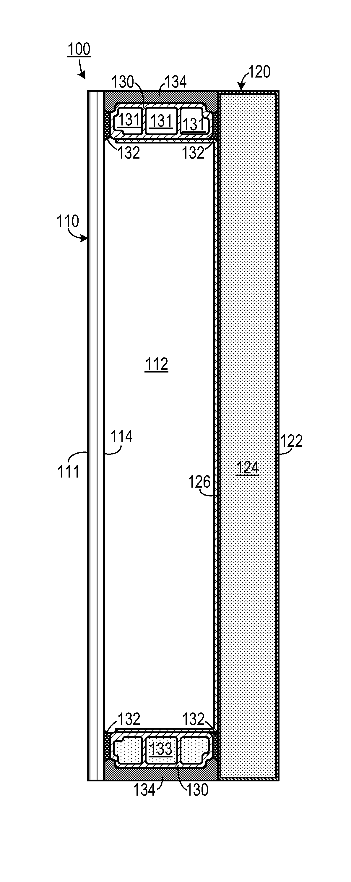
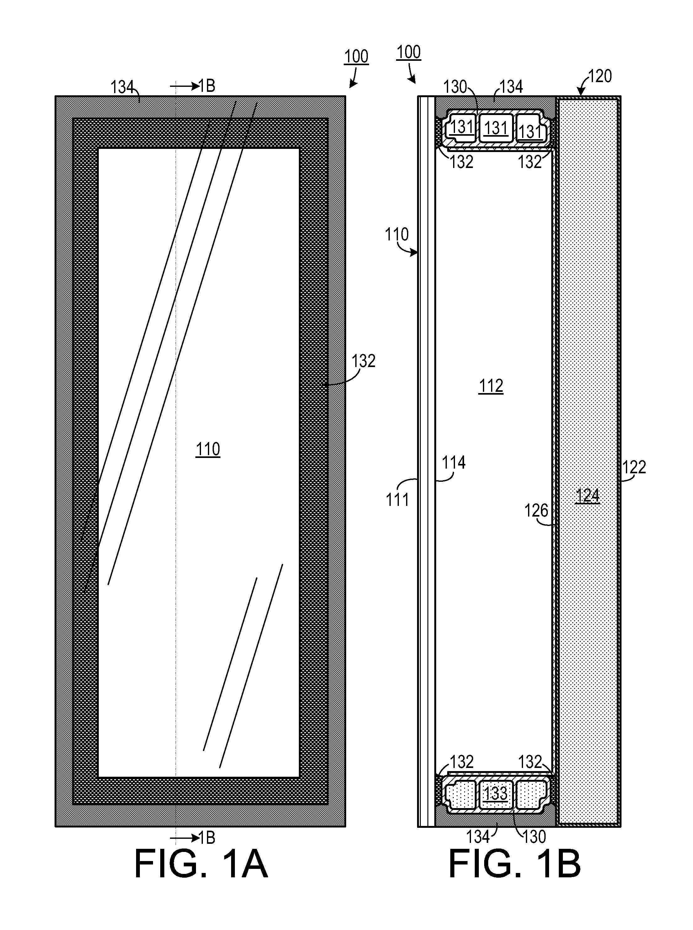
[0029]As shown in FIGS. 1A and 1B, one embodiment of a prefabricated shadow box 100 includes a vision glass panel 110 that is spaced apart from a back structure 120 so as to define a void 112 therebetween. The void 112 could include air, or it could include an inert gas (such as argon or krypton) to improve the thermal qualities of the shadow box 100. The vision glass panel 110 includes an outside (#1) surface 111 and an opposite insid...


PUM


Abstract

In a method of supplying an element for covering a non-vision area in a curtain wall on an architectural structure, a plurality of shadow boxes is prefabricated at a location remote from both a unitized curtain wall assembly shop and the architectural structure. The shadow boxes are prefabricated by sealing an interior spacer between a vision glass panel and a back structure. The back structure includes an insulating material surrounded by a rigid envelope. The vision glass panel, the back structure and the interior spacer define a hermetically sealed void therein. A structural seal is applied about the interior spacer and is affixed to the peripheral edge of the vision glass, the interior spacer and the back structure. The plurality of shadow boxes is then delivered to a selected one of the unitized curtain wall assembly shop and the architectural site.

Description

CROSS-REFERENCE TO RELATED APPLICATION(S)[0001]This application claims the benefit of U.S. Provisional Patent Application Ser. No. 61 / 757,396, filed Jan. 28, 2013, the entirety of which is hereby incorporated herein by reference.BACKGROUND OF THE INVENTION[0002]1. Field of the Invention[0003]The present invention relates to architectural devices and, more specifically, a shadow box for use in various building cladding systems including but not limited to unitized and stick system curtain wall, window wall, strongback, punched windows and other framed assemblies and rain screen assemblies.[0004]2. Description of the Related Art[0005]A curtain wall is a non-structural outer covering of a building. A curtain wall serves to provide a desired exterior appearance and to keep exterior environmental elements (e.g., wind, rain, etc.) out of the building. While a curtain wall will impart horizontal forces, such as wind loading, to the structural elements of the building, it does not bear the ...

Claims


Application Information

Patent Timeline
IPC IPC(8): E04B1/66E06B7/12E04B2/92
CPCE06B7/12E04B2/92E04B1/66E04C2/00E04B2/90E06B3/6617Y02A30/249Y02B80/22E04B2/88E04B2/96E06B3/6715E06B3/67326
Inventor WEINRYB, STEPHENMCCLELLAND, NEIL
Owner DOW CORNING CORP
Why Eureka
Try Eureka