Systems And Methods To Extend Gas Turbine Hot Gas Path Parts With Supercharged Air Flow Bypass

a technology of supercharged combined cycle and hot gas path, which is applied in the direction of engines, mechanical equipment, machines/engines, etc., can solve the problems of extending affecting the service life of equipment, etc., and achieves the effect of prolonging the life of hot gas path parts

Active Publication Date: 2014-07-31
GENERAL ELECTRIC CO
View PDF5 Cites 25 Cited by
  • Summary
  • Abstract
  • Description
  • Claims
  • Application Information

AI Technical Summary

Benefits of technology

[0007]In another embodiment, the invention relates to a method for extending hot gas path parts life in a turbine system. The method includes the steps of determining a desired load; determining an efficiency trade off; and determining a desired maintenance factor. The method further includes the steps of determining an amount of supercharging required to achieve the desired maintenance factor for the desired load. The method inclu...

Problems solved by technology

Factors including load conditions, equipment degradation, and ambient conditions may cause the generation unit to operate under less than optimal conditions.
One...

Method used


Image

  • Systems And Methods To Extend Gas Turbine Hot Gas Path Parts With Supercharged Air Flow Bypass
  • Systems And Methods To Extend Gas Turbine Hot Gas Path Parts With Supercharged Air Flow Bypass
  • Systems And Methods To Extend Gas Turbine Hot Gas Path Parts With Supercharged Air Flow Bypass

Examples


Embodiment Construction

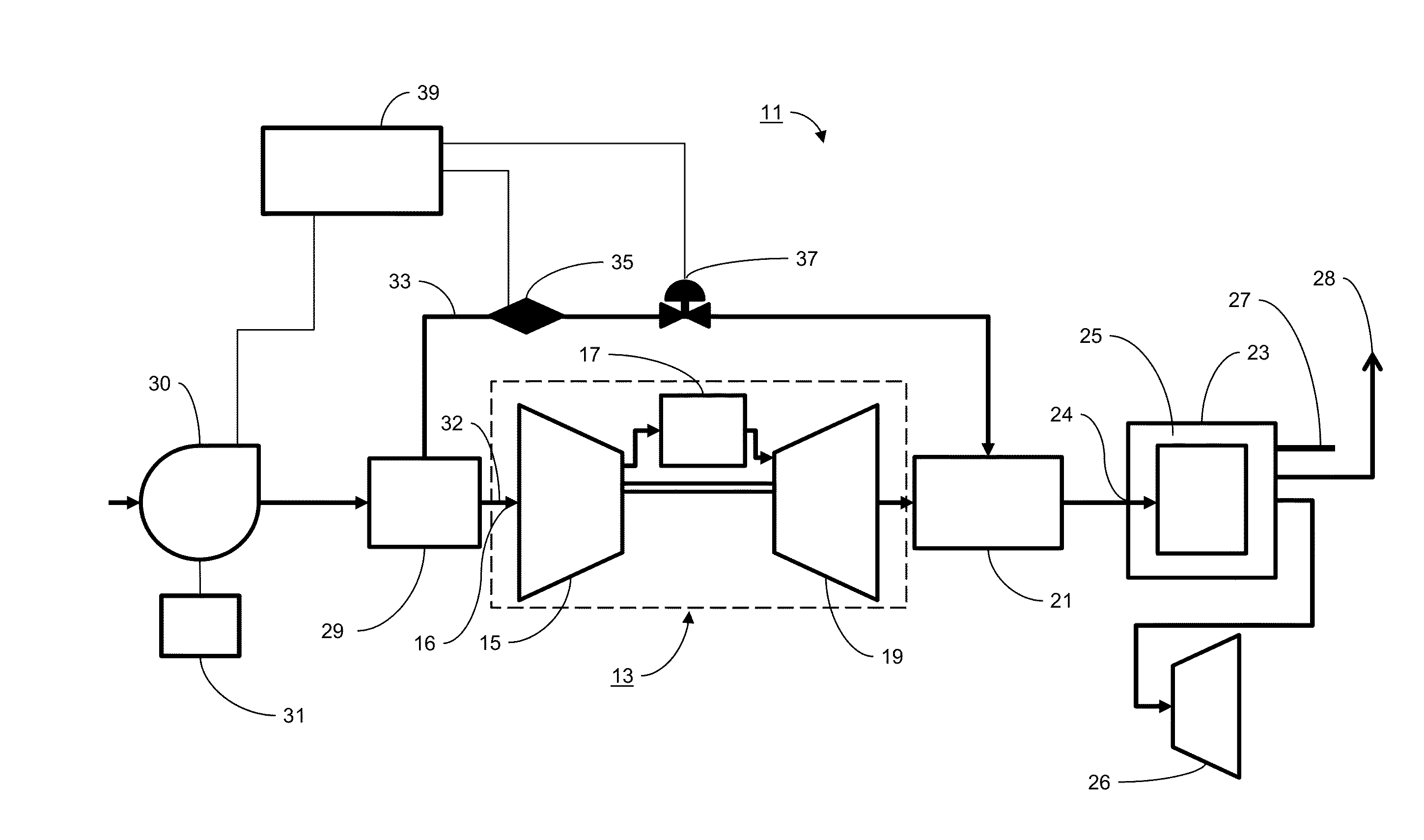
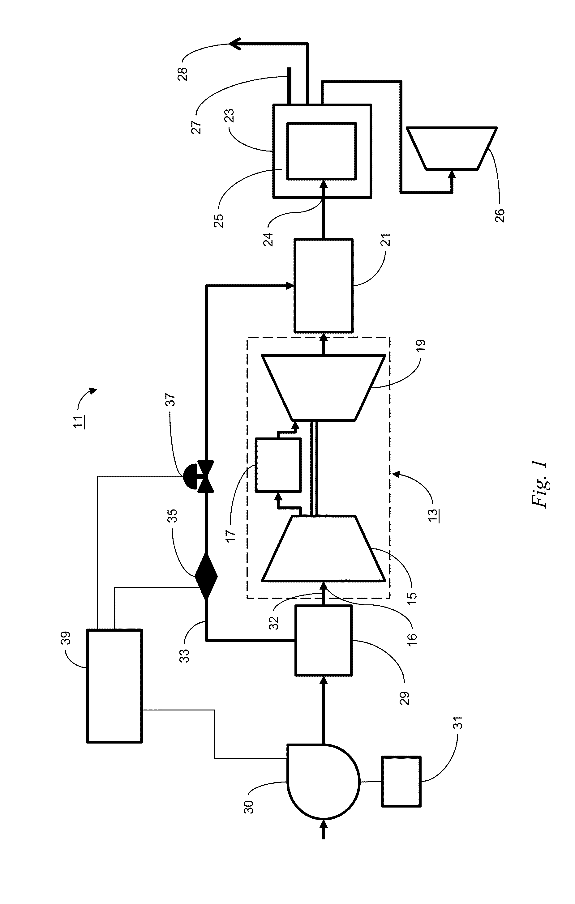
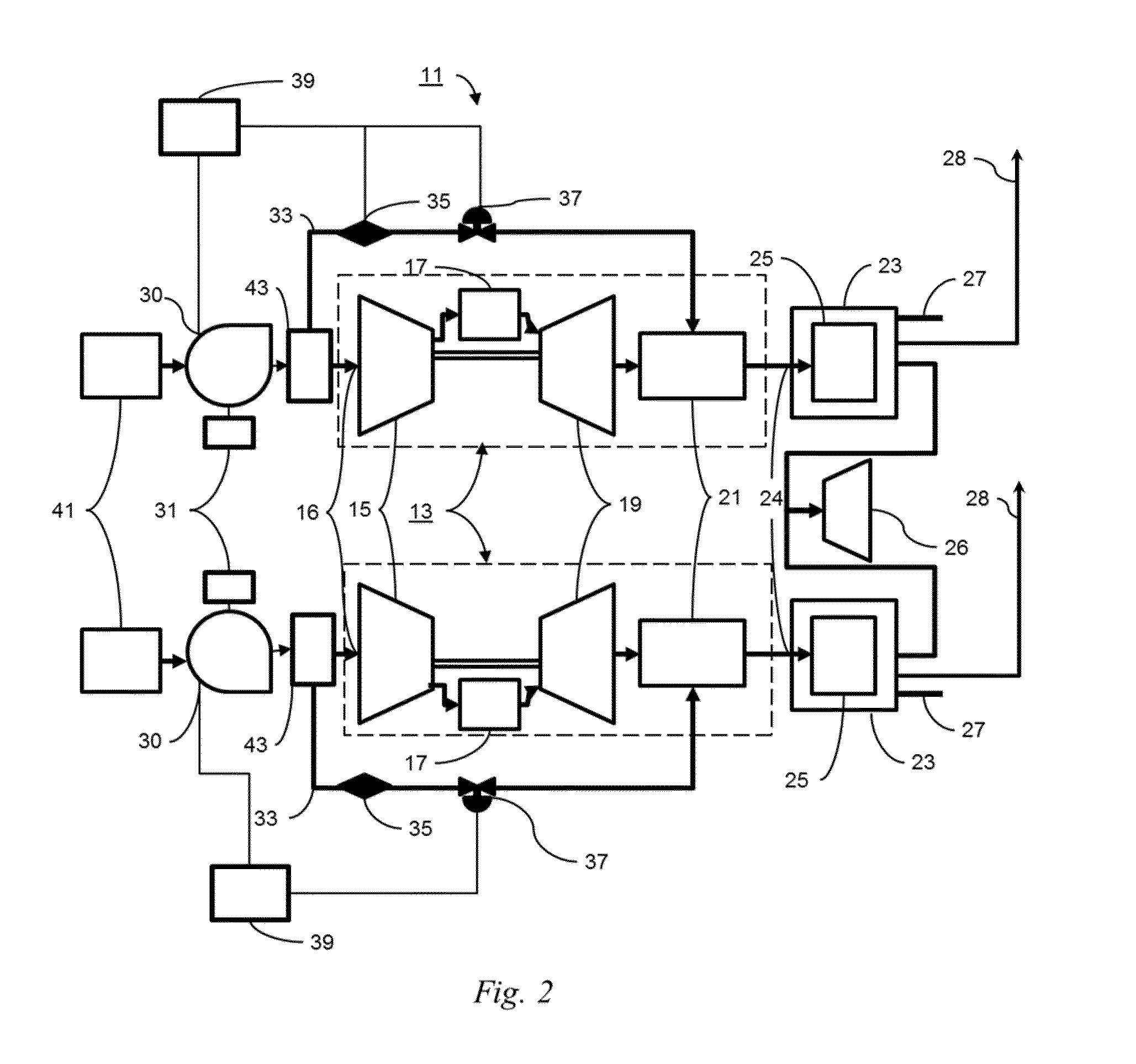
[0036]FIG. 1 is a schematic illustration of a supercharged combined cycle system with air bypass (SCCAB system 11) in accordance with one embodiment of the present invention. The SCCAB system 11 includes a gas turbine subsystem 13 that in turn includes a compressor 15, having a compressor inlet 16, a combustor 17 and a turbine 19. An exhaust duct 21 may be coupled to the turbine 19 and a heat recovery steam generator subsystem (HRSG 23). The HRSG 23 recovers heat from exhaust gases from the turbine 19 that are conveyed through HRSG inlet 24 to generate steam. The HRSG 23 may also include a secondary burner 25 to provide additional energy to the HRSG 23. Some of the steam and exhaust from the HRSG 23 may be vented to stack 27 or used to drive a steam turbine 26 and provide additional power. Some of the steam from the HRSG 23 may be transported through process steam outlet header 28 to be used for other processes. The SCCAB system 11 may also include an inlet house and cooling system ...


PUM


Abstract

A system and method for supercharging a combined cycle system includes a forced draft fan providing a variable air flow. At least a first portion of the air flow is directed to a compressor and a second portion of the airflow is diverted to a heat recovery steam generator. A control system controls the airflows provided to the compressor and the heat recovery steam generator. The system allows a combined cycle system to be operated at a desired operating state, balancing cycle efficiency and component life, by controlling the flow of air from the forced draft fan to the compressor and the heat recovery steam generator.

Description

CROSS-REFERENCE TO RELATED APPLICATIONS[0001]This application is related to application Ser. No. 13 / 485,216, titled GAS TURBINE COMPRESSOR INLET PRESSURIZATION AND FLOW CONTROL SYSTEM, filed jointly in the names of John Anthony Conchieri, Robert Thomas Thatcher, and Andrew Mitchell Rodwell and application Ser. No. 13 / 485,273, titled GAS TURBINE COMPRESSOR INLET PRESSURIZATION HAVING A TORQUE CONVERTER SYSTEM, filed jointly in the names of Sanji Ekanayake and Alston I. Scipio, each assigned to General Electric Company, the assignee of the present invention.TECHNICAL FIELD[0002]The subject matter disclosed herein relates to combined cycle power systems and more particularly to supercharged combined cycle systems with air flow bypass.BACKGROUND[0003]Combined cycle power systems and cogeneration facilities utilize gas turbines to generate power. These gas turbines typically generate high temperature exhaust gases that are conveyed into a heat recovery steam generator (HRSG) that produce...

Claims


Application Information

Patent Timeline
IPC IPC(8): F02C9/16
CPCF02C9/16F02C6/18F05D2220/70F05D2270/331F05D2270/112F05D2270/3061F02C9/18F05D2270/303Y02E20/14F02C9/28F02C6/08
Inventor EKANAYAKE, SANJISCIPIO, ALSTON ILFORDHARTMAN, STEVENDAVIS, DALE J.
Owner GENERAL ELECTRIC CO
Why Eureka
Try Eureka